2.9 Thermal Overload Protection
225
7UT613/63x Manual
C53000-G1176-C160-2
Ageing Rate Calcu-
lation
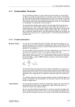
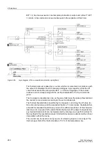
The life-time of a cellulose insulation refers to a temperature of 98
°
C or 208.4
°
F in
the direct environment of the insulation. Experience shows that an increase of 6K
means half the life-time. For a temperature which defers from the basic value of 98
°
C
(208.4
°
F), the relative ageing rate B is given by
The mean value of the relative ageing rate L is given by the calculation of the mean
value of a certain period of time, i.e. from T1 to T2
With constant rated load, the relative ageing rate L is equal to 1. For values greater
than 1, accelerated ageing applies, e.g. if L=2 only half of the life-time is expected
compared to the life-time under nominal load conditions.
According to IEC, the ageing range is defined from 80
°
C to 140
°
C. This is the oper-
ating range of the ageing calculation: Temperatures below 80
°
C (176
°
F) do not
extend the calculated ageing rate; values greater than 140
°
C (284
°
F) do not reduce
the calculated ageing rate.
The above-described relative ageing calculation only applies to the insulation of the
winding and cannot be used for other failure causes.
Output of Results
The hot-spot temperature is calculated for the winding which corresponds to the side
of the protected object configured for overload protection (Subsection 2.1.4, margin
heading „Further 3-phase Protection Functions“, address
442
). The calculation in-
cludes the current of that side and the cooling temperature measured at a certain mea-
suring point. The phase information is taken from the concerned phase in case of gen-
erators, motors, etc., or wye- or zigzag-connected transformer windings; in case of
delta-connected transformer windings the phase-difference currents are decisive
which correspond to the current flowing in the winding.
There are two thresholds which can be set. They output a warning (Stage 1) and an
alarm (Stage 2) signal. When the alarm signal is assigned to a trip output, it can also
be used for tripping the circuit breaker(s).
For the middle ageing rate, there is also a threshold for each of the warning and the
alarm signal.
The status can be read out from the operational measured values at any time. The in-
formation includes:
• hot-spot temperature for each winding in
°
C or
°
F (as configured),
• relative ageing rate expressed in per unit,
• load backup up to warning signal (Stage 1) expressed in per cent,
• load backup up to alarm signal (Stage 2) expressed in per cent.
Further limit values can be set on the thermobox itself, as in Section „RTD-Boxes for
Overload Recognition“
Содержание SIPROTEC 7UT613 series
Страница 16: ...Contents 16 7UT613 63x Manual C53000 G1176 C160 2 Literature 631 Glossary 623 Index 633 ...
Страница 30: ...1 Introduction 30 7UT613 63x Manual C53000 G1176 C160 2 ...
Страница 506: ...A Appendix 506 7UT613 63x Manual C53000 G1176 C160 2 7UT633 D E ...
Страница 508: ...A Appendix 508 7UT613 63x Manual C53000 G1176 C160 2 7UT633 P Q ...
Страница 510: ...A Appendix 510 7UT613 63x Manual C53000 G1176 C160 2 7UT635 D E ...
Страница 512: ...A Appendix 512 7UT613 63x Manual C53000 G1176 C160 2 7UT635 P Q ...
Страница 515: ...A 2 Terminal Assignments 515 7UT613 63x Manual C53000 G1176 C160 2 7UT633 B ...
Страница 516: ...A Appendix 516 7UT613 63x Manual C53000 G1176 C160 2 7UT633 B Figure A 7 General diagram 7UT633 panel surface mounting ...
Страница 517: ...A 2 Terminal Assignments 517 7UT613 63x Manual C53000 G1176 C160 2 7UT633 N ...
Страница 518: ...A Appendix 518 7UT613 63x Manual C53000 G1176 C160 2 7UT633 N Figure A 8 General diagram 7UT633 panel surface mounting ...
Страница 519: ...A 2 Terminal Assignments 519 7UT613 63x Manual C53000 G1176 C160 2 7UT635 B ...
Страница 520: ...A Appendix 520 7UT613 63x Manual C53000 G1176 C160 2 7UT635 B Figure A 9 General diagram 7UT635 panel surface mounting ...
Страница 521: ...A 2 Terminal Assignments 521 7UT613 63x Manual C53000 G1176 C160 2 7UT635 N ...
Страница 522: ...A Appendix 522 7UT613 63x Manual C53000 G1176 C160 2 7UT635 N Figure A 10 General diagram 7UT635 panel surface mounting ...
Страница 622: ...A Appendix 622 7UT613 63x Manual C53000 G1176 C160 2 ...
Страница 632: ...Literature 632 7UT613 63x Manual C53000 G1176 C160 2 ...


