


2 Functions
58
7UT613/63x Manual
C53000-G1176-C160-2
Address
224
ASSIGNM. 4M,3S
appears if
4
assigned measuring locations (address
212
) have been selected for
3
sides (address
213
). The following options are possi-
ble:
•
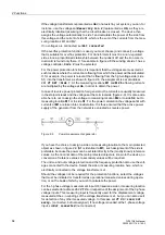
M1+M2,M3,M4
, i.e. the 4 measuring locations are assigned: M1 and M2 to side S1,
M3 to side S2, M4 to side S3. This corresponds to the examples in Figures 2-3 and
2-5.
•
M1,M2+M3,M4
, i.e. the 4 measuring locations are assigned: M1 to side S1, M2 and
M3 to side S2, M4 to side S3.
•
M1,M2,M3+M4
, i.e. the 4 measuring locations are assigned: M1 to side S1, M2 to
side S2, M3 and M4 to side S3.
Address
225
ASSIGNM. 4M,4S
appears if
4
assigned measuring locations (address
212
) have been selected for
4
sides (address
213
). Only one option is possible:
•
M1,M2,M3,M4
, i.e. the 4 measuring locations are assigned: M1 to side S1, M2 to
side S2, M3 to side S3, M4 to side S4.
Address
226
ASSIGNM. 5M,2S
appears if
5
assigned measuring locations (address
212
) have been selected for
2
sides (address
213
). The following options are possi-
ble:
•
M1+M2+M3,M4+M5
, i.e. the 5 measuring locations are assigned: M1 and M2 and
M3 to side S1, M4 and M5 to side S2.
•
M1+M2,M3+M4+M5
, i.e. the 5 measuring locations are assigned: M1 and M2 to side
S1, M3 and M4 and M5 to side S2.
•
M1+M2+M3+M4,M5
, i.e. the 5 measuring locations are assigned: M1 and M2 and
M3 and M4 to side S1, M5 to side S2.
•
M1,M2+M3+M4+M5
, i.e. the 5 measuring locations are assigned: M1 to side S1, M2
and M3 and M4 and M5 to side S2.
Address
227
ASSIGNM. 5M,3S
appears if
5
assigned measuring locations (address
212
) have been selected for
3
sides (address
213
). The following options are possi-
ble:
•
M1+M2,M3+M4,M5
, i.e. the 5 measuring locations are assigned: M1 and M2 to side
S1, M3 and M4 to side S2, M5 to side S3.
•
M1+M2,M3,M4+M5
, i.e. the 5 measuring locations are assigned: M1 and M2 to side
S1, M3 to side S2, M4 and M5 to side S3.
•
M1,M2+M3,M4+M5
, i.e. the 5 measuring locations are assigned: M1 to side S1, M2
and M3 to side S2, M4 and M5 to side S3.
•
M1+M2+M3,M4,M5
, i.e. the 5 measuring locations are assigned: M1 and M2 and
M3 to side S1, M4 to side S2, M5 to side S3.
•
M1,M2+M3+M4,M5
, i.e. the 5 measuring locations are assigned: M1 to side S1, M2
and M3 and M4 to side S2, M5 to side S3.
•
M1,M2,M3+M4+M5
, i.e. the 5 measuring locations are assigned: M1 to side S1, M2
to side S2, M3 and M4 and M5 to side S3.
Address
228
ASSIGNM. 5M,4S
appears if
5
assigned measuring locations (address
212
) have been selected for
4
sides (address
213
). The following options are possi-
ble:
•
M1+M2,M3,M4,M5
, i.e. the 5 measuring locations are assigned: M1 and M2 to side
S1, M3 to side S2, M4 to side S3, M5 to side S4.
•
M1,M2+M3,M4,M5
, i.e. the 5 measuring locations are assigned: M1 to side S1, M2
and M3 to side S2, M4 to side S3, M5 to side S4.
Содержание SIPROTEC 7UT613 series
Страница 16: ...Contents 16 7UT613 63x Manual C53000 G1176 C160 2 Literature 631 Glossary 623 Index 633 ...
Страница 30: ...1 Introduction 30 7UT613 63x Manual C53000 G1176 C160 2 ...
Страница 506: ...A Appendix 506 7UT613 63x Manual C53000 G1176 C160 2 7UT633 D E ...
Страница 508: ...A Appendix 508 7UT613 63x Manual C53000 G1176 C160 2 7UT633 P Q ...
Страница 510: ...A Appendix 510 7UT613 63x Manual C53000 G1176 C160 2 7UT635 D E ...
Страница 512: ...A Appendix 512 7UT613 63x Manual C53000 G1176 C160 2 7UT635 P Q ...
Страница 515: ...A 2 Terminal Assignments 515 7UT613 63x Manual C53000 G1176 C160 2 7UT633 B ...
Страница 516: ...A Appendix 516 7UT613 63x Manual C53000 G1176 C160 2 7UT633 B Figure A 7 General diagram 7UT633 panel surface mounting ...
Страница 517: ...A 2 Terminal Assignments 517 7UT613 63x Manual C53000 G1176 C160 2 7UT633 N ...
Страница 518: ...A Appendix 518 7UT613 63x Manual C53000 G1176 C160 2 7UT633 N Figure A 8 General diagram 7UT633 panel surface mounting ...
Страница 519: ...A 2 Terminal Assignments 519 7UT613 63x Manual C53000 G1176 C160 2 7UT635 B ...
Страница 520: ...A Appendix 520 7UT613 63x Manual C53000 G1176 C160 2 7UT635 B Figure A 9 General diagram 7UT635 panel surface mounting ...
Страница 521: ...A 2 Terminal Assignments 521 7UT613 63x Manual C53000 G1176 C160 2 7UT635 N ...
Страница 522: ...A Appendix 522 7UT613 63x Manual C53000 G1176 C160 2 7UT635 N Figure A 10 General diagram 7UT635 panel surface mounting ...
Страница 622: ...A Appendix 622 7UT613 63x Manual C53000 G1176 C160 2 ...
Страница 632: ...Literature 632 7UT613 63x Manual C53000 G1176 C160 2 ...


