


2.1 General
49
7UT613/63x Manual
C53000-G1176-C160-2
single-phase overcurrent protection is an autonomous protection function without any
relation to a specific side.
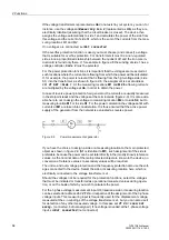
Figure 2-3 shows an example of a topology which in addition to the main protected
object (the three-winding transformer) has another protected object (the neutral reac-
tor) with a three-phase measuring location and an additional 1-phase measuring lo-
cation assigned to it. While in the main protected object one side can be fed from
various measuring locations (this is the case for the high-voltage side
S1
of the trans-
former, which is fed by
M1
and
M2
), no sides are defined for the additional protected
object. Nevertheless, other protection functions (not the differential protection) can act
on it, such as the overcurrent protection (3-phase on
M5
), the earth overcurrent pro-
tection (1-phase on
X4
), or the restricted earth fault protection, which compares the
triple zero sequence current from
M5
with the earth fault current of
X4
.
Figure 2-3
Topology of a three-winding transformer as main protected object and a neutral
reactor arranged outside of the protected zone as a further protected object;
right hand three-phase illustration of the neutral reactor
Sides:
S1
High voltage side of the main protected object (power transformer)
S2
Low voltage side of the main protected object (power transformer)
S3
Tertiary winding side of the main protected object (power transformer)
Measuring locations 3-phase, assigned:
M1
Measuring location, assigned to the main protected object, side 1
M2
Measuring location, assigned to the main protected object, side 1
M3
Measuring location, assigned to the main protected object, side 2
M4
Measuring location, assigned to the main protected object, side 3
Measuring locations 3-phase, non-assigned:
M5
Measuring location, not assigned to the main protected object, associated with the
neutral reactor
Auxiliary measuring locations, 1-phase:
X4
Measuring location, not assigned to the main protected object, associated with the
neutral reactor
Содержание SIPROTEC 7UT613 series
Страница 16: ...Contents 16 7UT613 63x Manual C53000 G1176 C160 2 Literature 631 Glossary 623 Index 633 ...
Страница 30: ...1 Introduction 30 7UT613 63x Manual C53000 G1176 C160 2 ...
Страница 506: ...A Appendix 506 7UT613 63x Manual C53000 G1176 C160 2 7UT633 D E ...
Страница 508: ...A Appendix 508 7UT613 63x Manual C53000 G1176 C160 2 7UT633 P Q ...
Страница 510: ...A Appendix 510 7UT613 63x Manual C53000 G1176 C160 2 7UT635 D E ...
Страница 512: ...A Appendix 512 7UT613 63x Manual C53000 G1176 C160 2 7UT635 P Q ...
Страница 515: ...A 2 Terminal Assignments 515 7UT613 63x Manual C53000 G1176 C160 2 7UT633 B ...
Страница 516: ...A Appendix 516 7UT613 63x Manual C53000 G1176 C160 2 7UT633 B Figure A 7 General diagram 7UT633 panel surface mounting ...
Страница 517: ...A 2 Terminal Assignments 517 7UT613 63x Manual C53000 G1176 C160 2 7UT633 N ...
Страница 518: ...A Appendix 518 7UT613 63x Manual C53000 G1176 C160 2 7UT633 N Figure A 8 General diagram 7UT633 panel surface mounting ...
Страница 519: ...A 2 Terminal Assignments 519 7UT613 63x Manual C53000 G1176 C160 2 7UT635 B ...
Страница 520: ...A Appendix 520 7UT613 63x Manual C53000 G1176 C160 2 7UT635 B Figure A 9 General diagram 7UT635 panel surface mounting ...
Страница 521: ...A 2 Terminal Assignments 521 7UT613 63x Manual C53000 G1176 C160 2 7UT635 N ...
Страница 522: ...A Appendix 522 7UT613 63x Manual C53000 G1176 C160 2 7UT635 N Figure A 10 General diagram 7UT635 panel surface mounting ...
Страница 622: ...A Appendix 622 7UT613 63x Manual C53000 G1176 C160 2 ...
Страница 632: ...Literature 632 7UT613 63x Manual C53000 G1176 C160 2 ...


