Hardware Descriptions
2.2 MCI2 board for 840Di sl
Manual
Commissioning Manual, 05/2008, 6FC5397–4CP10–4BA0
53
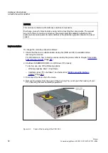
5.
Optional:
Remove interconnecting cable to the MCI board extension module, interface X2.
6.
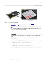
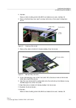
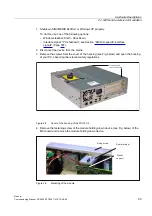
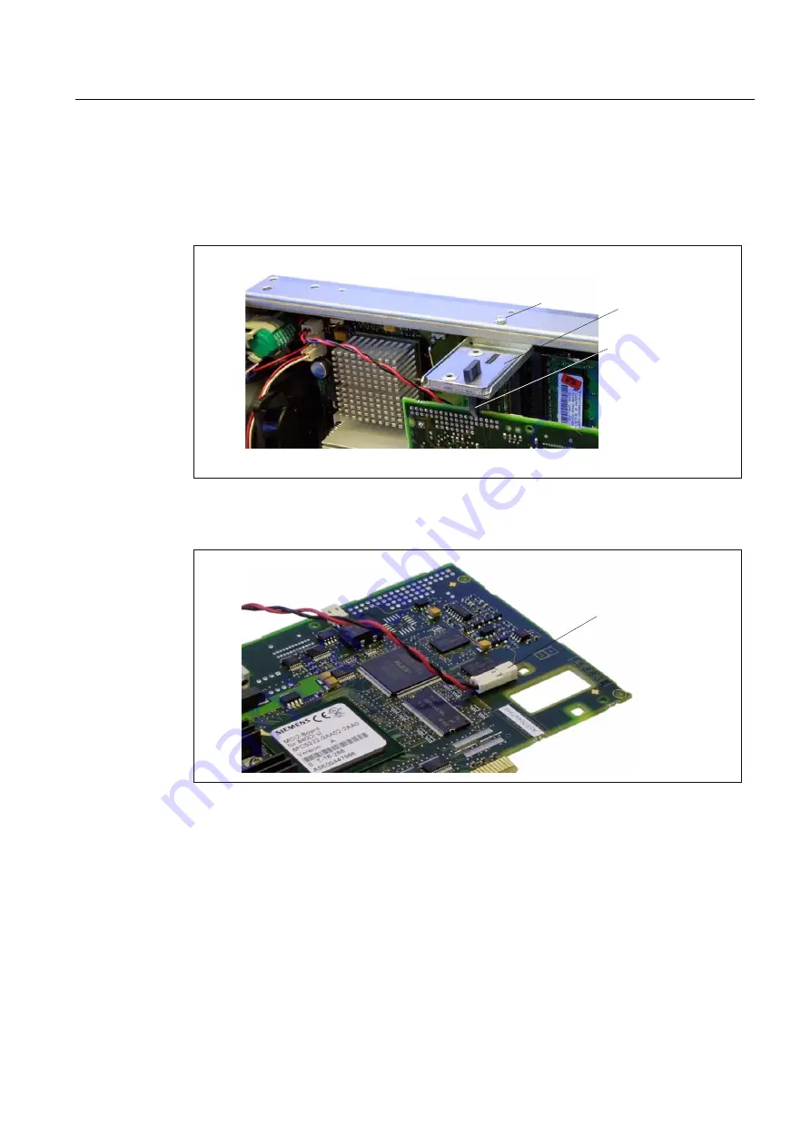
Remove the fastening screw (see Fig. below) and remove the module holding-down
device.
)L[LQJVFUHZ
%RDUGUHWDLQHU
3ODVWLF
VXSSRUW
Figure 2-4
Mounting of the module
7.
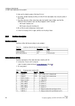
Remove the cable connection X3 (backup battery) from the module.
;%DFNXSEDWWHU\
Figure 2-5
Backup battery connector
8.
Loosen the fastening screw on the cover plate of the module and remove the module
while observing ESD measures.
9.
Insert the new module into the appropriate slot on the mother board and fasten it using
the fastening screw on the cover plate.
10.
Insert the cable connection X3 (backup battery) into the module.
11.
Re-attach the board retainer.
12.
Optional:
Remove interconnecting cable to the MCI board extension module, interface X2.
Содержание SINUMERIK 840Di sl
Страница 118: ...Configuration 3 3 Connection overview Manual 118 Commissioning Manual 05 2008 6FC5397 4CP10 4BA0 ...
Страница 148: ...Power On and Power Up 5 7 License management Manual 148 Commissioning Manual 05 2008 6FC5397 4CP10 4BA0 ...
Страница 186: ...PLC commissioning 6 8 Load configuration in PG PLC STEP 7 Manual 186 Commissioning Manual 05 2008 6FC5397 4CP10 4BA0 ...
Страница 344: ...Drive commissioning SINAMICS 9 5 Basic principles Manual 344 Commissioning Manual 05 2008 6FC5397 4CP10 4BA0 ...
Страница 624: ...Glossary Manual 624 Commissioning Manual 05 2008 6FC5397 4CP10 4BA0 ...

