PROFIBUS DP Communication
8.3 Creating a PROFIBUS configuration
Manual
Commissioning Manual, 05/2008, 6FC5397–4CP10–4BA0
239
8.3
Creating a PROFIBUS configuration
8.3.1
Requirement
S7 project
The procedure described in this Section for setting up the PROFIBUS configuration as well
as the parameterization of various components (for example, SINAMIC drives, ADI4), is
based on an S7 project created using the description in Chapter "Create PROFIBUS
Configuration"
The following status of the S7 project is required:
●
S7 project is has been set up (name: SIN840Di sl)
●
Station 300 has been set up
●
Interface (X102) PROFIBUS is parameterized (optional)
●
Interface (X101) PROFIBUS is parameterized
●
Input/output data areas of the NC are parameterized
Note
The instructions given in this Section are essentially limited to the special characteristics
of the SINUMERIK 840Di sl. For more details about working with SIMATIC STEP 7
please refer to the relevant SIMATIC documentation or online help.
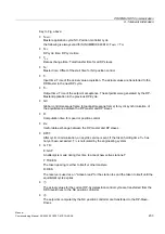
Starting HW Config
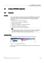
Start "HW Config" by opening the station and double-clicking the hardware icon.
6,1'LVOLQVWDOODWLRQSDWK!?VWHS?VSURM?6,1'LVO
6,1'LVO
6,0$7,&
3/&'3$-
+DUGZDUH
3/&'3$-
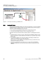
Figure 8-4
Inserting the SIMATIC 300 station
In HW Config, now insert the required PROFIBUS modules from the hardware catalog into
the S7 project.
Содержание SINUMERIK 840Di sl
Страница 118: ...Configuration 3 3 Connection overview Manual 118 Commissioning Manual 05 2008 6FC5397 4CP10 4BA0 ...
Страница 148: ...Power On and Power Up 5 7 License management Manual 148 Commissioning Manual 05 2008 6FC5397 4CP10 4BA0 ...
Страница 186: ...PLC commissioning 6 8 Load configuration in PG PLC STEP 7 Manual 186 Commissioning Manual 05 2008 6FC5397 4CP10 4BA0 ...
Страница 344: ...Drive commissioning SINAMICS 9 5 Basic principles Manual 344 Commissioning Manual 05 2008 6FC5397 4CP10 4BA0 ...
Страница 624: ...Glossary Manual 624 Commissioning Manual 05 2008 6FC5397 4CP10 4BA0 ...

