Ethernet communication
7.6 HT 8
Manual
Commissioning Manual, 05/2008, 6FC5397–4CP10–4BA0
213
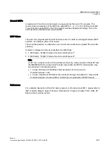
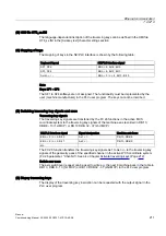
The value 0 is to be entered as axis number in the table for traversing key signals that are
not supposed to act on any machine axis.
Specifying an invalid axis number can make the PLC switch to the "stop" state. There is no
validation for invalid axis numbers.
Changeover axes
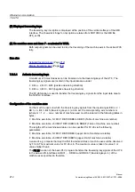
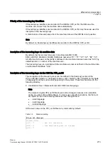
A softkey is pre-configured in HT 8 for switching the axes, e.g. the next six machine axes.
●
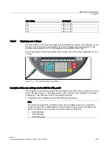
"U" key > vertical "Changeover axis key" softkey.
The following input signal is set via the softkey:
●
EB n + 2, Bit 6 = 1 (switch axes)
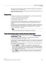
The actual switching must be undertaken by the user (machine manufacturer) in the PLC
user program. For this, the machine axis table must be overwritten with the new axis
numbers.
With active WCS, it is assumed implicitly In FC 26, that the first 3 axes in the machine axis
table are geometry axes. If this is not the case e.g. after the axis switchover, then the user
(machine manufacturer) must set the following output signal in the PLC user program:
●
AB n + 2, Bit 6 (Axes 7 - n selected)
Note
A machine axis table should then be overwritten if no axis traverses.
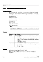
Transfer of the traversing key signals as a function of the active coordinate system
The switchover between MCS and WCS is described in Chapter: MCS/WCS coordinate
system switchover (Page 218)
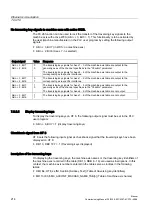
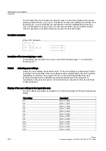
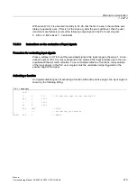
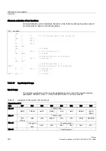
The active coordinate system is displayed by FC 26 in the following output signal:
●
AB n + 0, Bit 0 (MCS/WCS) with 0 = MCS, 1 = WCS
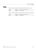
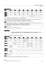
With active MCS, the traversing key signals of axes 1 to 6 are transferred to the axis-specific
interfaces (DB31, ... DBX4.6 and DBX4.7 (traversing keys +/-)) of the axes specified in the
machine axis table.
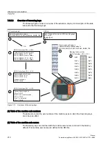
For active WCS, it is assumed that the Axes 1 to 3 of the machine axis table are geometry
axes. Hence the traversing key signals:
●
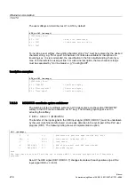
of the axes 1 - 3 (EB n + 2 / 3, Bit 0 - Bit 2) are transferred to the interface of the
geometry axes in DB 21, ... DBB 12 + (n * 4), with n = 0, 1, 2), Bit 6 and Bit 7 (traversing
keys +/-) of the channel specified via the "ChanNo" parameter. The assignment of the
traversing key signals of axes 1, 2 and 3 to the geometry axes 1, 2 and 3 of the channel
is permanent and cannot be changed.
●
The axes 4 - 6 (EB n + 2 / 3, Bit 3 - Bit 5) are transferred to the axis-specific interfaces
(DB31, ... DBX4.6 and DBX4.7 (traversing keys +/-)) of the 4 - 6 axes entered in the
machine axis table.
Содержание SINUMERIK 840Di sl
Страница 118: ...Configuration 3 3 Connection overview Manual 118 Commissioning Manual 05 2008 6FC5397 4CP10 4BA0 ...
Страница 148: ...Power On and Power Up 5 7 License management Manual 148 Commissioning Manual 05 2008 6FC5397 4CP10 4BA0 ...
Страница 186: ...PLC commissioning 6 8 Load configuration in PG PLC STEP 7 Manual 186 Commissioning Manual 05 2008 6FC5397 4CP10 4BA0 ...
Страница 344: ...Drive commissioning SINAMICS 9 5 Basic principles Manual 344 Commissioning Manual 05 2008 6FC5397 4CP10 4BA0 ...
Страница 624: ...Glossary Manual 624 Commissioning Manual 05 2008 6FC5397 4CP10 4BA0 ...

