Drive Optimization with HMI Advanced
14.4 Frequency response measurements
Manual
516
Commissioning Manual, 05/2008, 6FC5397–4CP10–4BA0
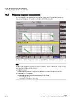
Measurement: Reference and interference frequency response
The response range should be as wide as possible and without resonance. It may be
necessary to use bandstop or low-pass filters. Pay special attention to resonances within the
speed controller limit frequency range (stability limit approx. 200-500 Hz).
Alternatively, the interference frequency response can be recorded in order to assess how
well the control suppresses interference.
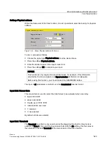
Measuring parameters
●
Amplitude
This parameter determines the magnitude of the test signal amplitude. This should give
rise to only a very low speed of a few (approximately 1 to 2) rev/min at the motor end.
●
Bandwidth
The bandwidth parameter is used to set the analyzed frequency range. The larger this
value, the finer the frequency resolution and the longer the measurement time. The
maximum value is specified by the position controller cycle (T
position controller
): Bandwidth
max
[Hz] = 1 / (2 * T
position controller
[sec])
Example:
Position controller cycle: 2 ms
Bandwidth
max
= 1 / (2 * 2*10
-3
) = 250 Hz
●
Averaging
The accuracy of the measurement and measurement duration increase with this value. A
value of 20 is normally suitable.
●
Settling time
This value represents the delay between recording of the measured data and injection of
the test setpoint and offset. A value of between 0.2 and 1 s is recommended. Do not set
too low a value for the settling times or the frequency response and phase diagrams will
be distorted.
●
Offset
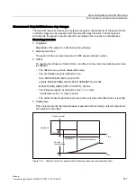
The measurement requires a slight speed offset of a few motor revolutions per minute.
The offset must be set to a higher value than the amplitude.
–
The offset is run up via an acceleration ramp.
–
The acceleration value is defined for one
Axis: MD 32300 $MA_MAX_AX_ACCEL
spindle: MD 35200 $MA_GEAR_STEP_SPEEDCTRL_ACCEL
MD 35210 $MA_GEAR_STEP_POSCTRL_ACCEL
–
The following applies: Acceleration value = 0, no ramp
Acceleration value > 0, ramp is active
–
The actual measuring function becomes active only when the offset value is reached.
Содержание SINUMERIK 840Di sl
Страница 118: ...Configuration 3 3 Connection overview Manual 118 Commissioning Manual 05 2008 6FC5397 4CP10 4BA0 ...
Страница 148: ...Power On and Power Up 5 7 License management Manual 148 Commissioning Manual 05 2008 6FC5397 4CP10 4BA0 ...
Страница 186: ...PLC commissioning 6 8 Load configuration in PG PLC STEP 7 Manual 186 Commissioning Manual 05 2008 6FC5397 4CP10 4BA0 ...
Страница 344: ...Drive commissioning SINAMICS 9 5 Basic principles Manual 344 Commissioning Manual 05 2008 6FC5397 4CP10 4BA0 ...
Страница 624: ...Glossary Manual 624 Commissioning Manual 05 2008 6FC5397 4CP10 4BA0 ...

