

NC Commissioning with HMI Advanced
11.5 Axes and spindles
Manual
392
Commissioning Manual, 05/2008, 6FC5397–4CP10–4BA0
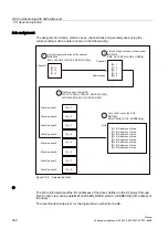
ADI4
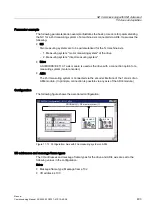
With an ADI4 module you can operate up to 4 drives with analog setpoint interface on an
isochronous PROFIBUS.
The 611U-specific functions (Bit0 - Bit3) and effects of OFF2/OFF3 on the signal
"driveReady" (Bit11) must be disabled for these drives. The machine data must be set for
every drive operated via ADI4:
●
MD13070 $MN_DRIVE_FUNCTION_MASK[n] = 80F
H
NOTICE
The 611U-specific functions (Bit0 - Bit3) and effects of OFF2/OFF3 on the signal
"driveReady" (Bit11) must be disabled for all drives connected via ADI4.
•
MD13070 $MN_DRIVE_FUNCTION_MASK[n] = 80F
H
Drive type DP
The NC attempts to ascertain the drive type for each parameterized PROFIBUS drive
independently. The drive type is shown in the following machine data:
●
MD13080 $MN_DRIVE_TYP_DP[n] (drive type PROFIBUS DP)
The following drive types are displayed by the NC:
1.
VSA (SRM: Synchronous Rotary Motor)
2.
HSA (ARM: Asynchronous Rotary Motor)
3.
Linear drive
If the NC is not able to determine the drive type because the drive e.g. does not support any
acyclic communication or it was switched off via machine data MD13070
$MN_DRIVE_FUNCTION_MASK (used DP functions), then the following value is displayed:
●
0: No drive or drive type not known
Drive type DP: 4
If drive type 0 is displayed for a parameterized PROFIBUS drive, the value can be manually
set to the following:
●
4: Drive does not support acyclic communication
Setting the drive type to value 4 has the following effects in HMI Advanced:
●
Drive parameters
No drive parameters are read.
●
Current and speed controller cycle
There is no display of current and speed controller cycle.
●
Drive type
ANA is displayed as the drive type.
●
Speed control loop
The dialog box for measuring the speed control loop only offers measurements of the
reference frequency response and setpoint step change.
●
Current control loop
The dialog box for measuring the current control loop is not offered.
Содержание SINUMERIK 840Di sl
Страница 118: ...Configuration 3 3 Connection overview Manual 118 Commissioning Manual 05 2008 6FC5397 4CP10 4BA0 ...
Страница 148: ...Power On and Power Up 5 7 License management Manual 148 Commissioning Manual 05 2008 6FC5397 4CP10 4BA0 ...
Страница 186: ...PLC commissioning 6 8 Load configuration in PG PLC STEP 7 Manual 186 Commissioning Manual 05 2008 6FC5397 4CP10 4BA0 ...
Страница 344: ...Drive commissioning SINAMICS 9 5 Basic principles Manual 344 Commissioning Manual 05 2008 6FC5397 4CP10 4BA0 ...
Страница 624: ...Glossary Manual 624 Commissioning Manual 05 2008 6FC5397 4CP10 4BA0 ...