PROFIBUS DP Communication
8.6 DP slave MCP 310
Manual
Commissioning Manual, 05/2008, 6FC5397–4CP10–4BA0
255
8.6.2
Parameterization of the MCP
Interfaces
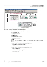
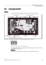
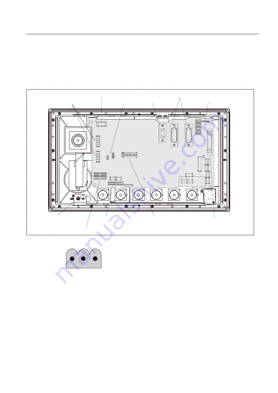
In the following figure, the interfaces are shown on the rear side of the module:
COM-Board
&20%RDUG
5RWDU\VZLWFK;;
3RZHUVXSSO\;
/('V
352),%86;
+DQGZKHHOV;;
+DQGZKHHOVLJQDOW\SH6
7HUPLQDWLRQ
(TXLSRWHQWLDOERQGLQJFRQGXFWRU
&XVWRPHUVSHFRSHUDWLRQHOHPHQWV;;
.H\VZLWFK;
6',3VZLWFK
'LUHFWNH\V;
Figure 8-11 Rear of the MCP 310 showing the control and display elements and the interfaces
6KLHOG03
Figure 8-12 Connection overview: Power supply X10
For a detailed description of the electrical and mechanical design and of the machine control
panel interfaces, please refer to:
References:
/BH/ Operator Components Manual, Chapter "MCP 310 Machine Control Panel"
Содержание SINUMERIK 840Di sl
Страница 118: ...Configuration 3 3 Connection overview Manual 118 Commissioning Manual 05 2008 6FC5397 4CP10 4BA0 ...
Страница 148: ...Power On and Power Up 5 7 License management Manual 148 Commissioning Manual 05 2008 6FC5397 4CP10 4BA0 ...
Страница 186: ...PLC commissioning 6 8 Load configuration in PG PLC STEP 7 Manual 186 Commissioning Manual 05 2008 6FC5397 4CP10 4BA0 ...
Страница 344: ...Drive commissioning SINAMICS 9 5 Basic principles Manual 344 Commissioning Manual 05 2008 6FC5397 4CP10 4BA0 ...
Страница 624: ...Glossary Manual 624 Commissioning Manual 05 2008 6FC5397 4CP10 4BA0 ...

