background image

Hardware Descriptions 


2.1 Overview of hardware components 


Manual 

46


Commissioning Manual, 05/2008, 6FC5397–4CP10–4BA0 

SIMODRIVE drives 


SIMODRIVE 611 universal 
with options module Motion Control with PROFIBUS DP 


SIMODRIVE 611 universal E 
with options module Motion Control with PROFIBUS DP 


SIMODRIVE POSMO CD/CA 


SIMODRIVE POSMO SI 


SIMODRIVE POSMO A 

For detailed ordering information on various drives, see: 
References: 
/BU/ SINUMERIK & SIMODRIVE, Order Document, Catalog NC 60 

Содержание SINUMERIK 840Di sl

Страница 1: ...VE 10 NC Commissioning with HMI Advanced 11 Alarm and message texts 12 Axis and Spindle Test Run 13 Drive Optimization with HMI Advanced 14 User data backup Series commissioning 15 Software installation update and data backup 16 License management 17 840Di specific data and functions 18 Appendix A SINUMERIK 840Di sl Manual Commissioning Manual 05 2008 6FC5397 4CP10 4BA0 Valid for SINUMERIK 840Di s...

Страница 2: ...Commissioning and operation of a device system may only be performed by qualified personnel Within the context of the safety notes in this documentation qualified persons are defined as persons who are authorized to commission ground and label devices systems and circuits in accordance with established safety practices and standards Prescribed Usage Note the following WARNING This device may only ...

Страница 3: ...is intended for manufacturers end users of machine tools and production machines who use SINUMERIK 840Di sl and SINAMICS S120 Benefits This manual provides detailed information required for the configuration and commissioning of a SINUMERIK 840Di sl system This manual describes the control system design and the interfaces of the individual components The commissioning procedure for SINUMERIK 840Di...

Страница 4: ...y this documentation does not contain all detailed information about all types of the product and cannot cover every conceivable case of installation operation or maintenance Technical support If you have any technical questions please contact our hotline Europe Africa Phone 49 180 5050 222 Fax 49 180 5050 223 Internet http www siemens com automation support request America Phone 1 423 262 2522 Fa...

Страница 5: ...Order No 15257461or at the relevant branch office of the A D MC group of Siemens AG Danger notices The following notices are intended firstly for your personal safety and secondly to prevent damage occurring to the product described or any connected devices and machines Non observance of the warnings can result in severe personal injury or property damage DANGER Only appropriately qualified person...

Страница 6: ...telephones with a transmitting power of 1 W may lead to incorrect functioning of the devices Connecting cables and signal lines should be installed so that inductive and capacitive interference does not in any way impair the automation and safety functions SINAMICS equipment with three phase motors conforms to EMC Directive 89 336 EEC in the configurations specified in the associated EC Certificat...

Страница 7: ...d export version 36 1 5 840Di startup 38 1 5 1 Menu command Windows 39 2 Hardware Descriptions 43 2 1 Overview of hardware components 43 2 2 MCI2 board for 840Di sl 47 2 2 1 Assembly 47 2 2 2 Interface description 48 2 2 3 Replace module 50 2 2 4 Technical data 54 2 3 MCI board extension slot variation 56 2 3 1 Assembly 56 2 3 2 Installation instructions 58 2 3 3 Interface description 60 2 3 4 Tec...

Страница 8: ...U components 111 3 2 Electrical design 112 3 2 1 MCI board and PROFIBUS DP 112 3 2 2 MCI board extension 113 3 2 3 PCU 50 3 114 3 3 Connection overview 115 3 3 1 MCI board and MCI board extension 115 3 3 2 PCU50 117 4 EMC and ESD Measures 119 4 1 RI suppression measures 119 4 2 ESD measures 120 5 Power On and Power Up 121 5 1 Preparing for commissioning 121 5 1 1 Checklist 121 5 1 2 Recommended se...

Страница 9: ...PLC program 150 6 1 4 Installing the PLC basic program library 151 6 1 5 STEP 7 example projects 151 6 1 6 PLC user program 153 6 2 Commissioning 155 6 2 1 Basic requirements 155 6 2 2 External communications link Ethernet 156 6 2 3 Local communications link SOFTMC 156 6 2 4 Check PLC status and communication interface 157 6 2 5 First commissioning 157 6 3 Creating a SIMATIC S7 project 160 6 3 1 C...

Страница 10: ...e power supply unit 202 7 6 3 Parameterization of the HT 8 via the TCU firmware 203 7 6 4 Parameterization of the HT 8 via the system network center 204 7 6 5 Linking to the basic PLC and user program 206 7 6 5 1 Linking to the basic PLC program FB1 206 7 6 5 2 Signal transmission from to NC PLC interface FC26 208 7 6 5 3 Overview of traversing keys 210 7 6 5 4 Activate traversing keys 212 7 6 5 5...

Страница 11: ... and user program 264 8 6 6 Input Output image 267 8 7 DP slave MCP 483 270 8 7 1 Conditions for general commissioning 270 8 7 2 Parameterization of the MCP 272 8 7 3 Functions of the machine control panel 274 8 7 4 Configure MCP 483 DP slave 275 8 7 5 Linking to the basic PLC and user program 280 8 7 6 Input Output image 283 8 8 ADI4 DP slave 286 8 8 1 SlaveOM 286 8 8 2 Inserting the DP slave 286...

Страница 12: ...ore than 6 drives 333 9 3 1 Configuration 333 9 3 2 Basic commissioning 334 9 3 3 Drives of Control Unit 2 Additional BICO interconnection 335 9 4 Further terminal assignments 337 9 4 1 Advice on terminal assignment 1 CU X122 337 9 4 2 Advice on terminal assignment 1 CU X132 338 9 4 3 Advice on terminal assignment 2 up to nth CU X122 338 9 4 4 Advice on interconnection 1 CU with 2nd to nth CU 340 ...

Страница 13: ...tion controller 413 11 5 15 Speed setpoint matching 417 11 5 16 Drift compensation 420 11 5 17 Axis velocity matching 421 11 5 18 Axis monitoring 423 11 5 19 Axis homing 431 11 5 20 Spindle basic data 441 11 5 21 Setpoint actual value channels of spindle 444 11 5 22 Gear stages 444 11 5 23 Spindle measuring systems 445 11 5 24 Speeds and setpoint adjustment for spindle 447 11 5 25 Positioning the ...

Страница 14: ...3 Axis and Spindle Test Run 501 13 1 Requirements 501 13 1 1 Drives SINAMICS S120 501 13 1 2 Drives SIMODRIVE 502 13 1 3 NC PLC interface signals 502 13 2 Axis dry run 504 13 3 Spindle dry run 505 14 Drive Optimization with HMI Advanced 507 14 1 Overview 507 14 2 Measuring functions 508 14 3 Special functions 510 14 4 Frequency response measurements 512 14 4 1 Measurement of current control loop 5...

Страница 15: ...ation of the SINUMERIK 840Di sl applications 561 17 License management 563 17 1 Basic principles 563 17 1 1 Important terms 563 17 1 2 Overview 564 17 1 3 Web License Manager 565 17 1 4 Automation License Manager 565 17 1 5 License database 565 17 1 6 MCI board and hardware serial number 567 17 1 7 SINUMERIK License Key 568 17 1 8 Browser settings for using the A D Mall 569 17 1 9 Proxy settings f...

Страница 16: ...20 and expanded message frame configuration 592 18 2 5 Project design SIMODRIVE 595 18 2 6 Constraints 600 18 2 7 Data descriptions MD system variable 602 18 2 8 Interrupts 603 18 3 Travel to fixed stop with high resolution torque reduction 604 18 3 1 Description of functions 604 18 3 2 Comparison 605 18 3 3 Parameter assignment SINAMICS S120 605 18 3 4 Parameter assignment SIMODRIVE 606 18 3 5 Pa...

Страница 17: ... based automation solutions and is generally designed especially for applications with the following requirements Decentralized automation solutions in the fields of PLC I Os and drives Fully PC integrated control owing to increased integratability in the target or current automation environment 2SHUDWRU 3DQHO IURQW H J 23 3 8 86 VWDQGDUG 2 0 RDUG WHQVLRQ 2SWLRQ 0 RDUG RPSDQ QHWZRUN 0HDVXULQJ 3XOV...

Страница 18: ... possible to combine the named system components with older versions 1 1 2 System software packages and quantity structures System software packages The following system software packages are available for SINUMERIK 840Di sl 6 axes system software 20 axes system software Quantity framework The system software packages are each designed for the following quantity structures 6 axes 20 axes Basic con...

Страница 19: ...s The PCU 50 3 has the following slots 1 x PCI length max 175 mm occupied with option MCI board extension and MCI board extension slot variant 1 x PCI length max 265 mm occupied by the MCI board MCI2 board The MCI2 Board called only as MCI Board from now on is a small PCI slot card with integrated SIMATIC S7 compatible CPU PLC317 2 DP as the DP Master with routing capability The MCI board has the ...

Страница 20: ...into a slot in the PCU and is connected to the MCI board via a ribbon cable Digital drives SINUMERIK 840Disl is available with the components from the new SINAMICS range of drives offering the following characteristics SINAMICS S120 The drive components from the SIMODRIVE range of drives offering the following characteristics can also be used SIMODRIVE 611 universal and universal E with option mod...

Страница 21: ... So SIEMENS has developed a procedure that allows operation of NC system software in hard real time without making it necessary to modify Windows XP see Subsection Real time properties Page 23 NC system software The NC system software mostly has the same functionality as the SINUMERIK 840D It comprises both simple Motion Control processes positioning and linear interpolation and complex automation...

Страница 22: ...d optionally SINUMERIK HMI Advanced HMI Advanced is the SINUMERIK standard user interface especially for machine tools SIMATIC Protool Pro and Protool Pro Option SINUMERIK SIMATIC Protool Pro and Protool Pro Option SINUMERIK are configuring packages packets for creating the technology specific user interfaces The ProTool Pro runtime system is the prerequisite for running a configured operator inte...

Страница 23: ...00 µs we cannot guarantee that the NC system software will operate correctly The system will respond appropriately for the magnitude of the real time violation Display of an error message Alarm with axis stop from the NC Alarm and drive independent stopping of the axes The real time response can be monitored in the NCK latency displays in the system diagnostics of the 840Di Startup see Section 840...

Страница 24: ...on may occur in the real time response 1 1 6 System integrity To offer high quality and wide functionality of the entire system SINUMERIK 840Disl comes completely configured and ready to operate For this purpose the system components used are subject to a certification procedure with Siemens as the system manufacturer The certification process establishes and documents the real time features of th...

Страница 25: ... continue or step machining After completion of machining the PLC user program can request a shutdown of the PC by sending the PC shutdown interface signal The PC shutdown interface signal causes the following actions Retentive NC and PLC data are stored NC and PLC are closed down The Windows XP Blue Screen is displayed Execute reboot of the PCU optional The behavior of Windows XP in the event of ...

Страница 26: ... following message box is displayed Alarm Power Fail detected NCK PLC restart with OK SINUMERIK 840Di sl NCK PLC NOTICE The following is to be taken into account Power supply A supply voltage of the PCU of at least 24 V is required to ensure consistency of the NC and PLC user data References BH Operator components Manual Subsection PCU 50 3 UPS system The internal power backup time after a power f...

Страница 27: ...emperature change of at least 3 C before the threshold value is necessary so that the alarm is reset If the temperature alarm occurs the user and or the machine manufacturer PLC user program must decide whether to interrupt machining and end and shut down the SINUMERIK 840Di sl 1 1 8 Switch off Windows XP To ensure safe operation of the SINUMERIK 840Di sl Windows XP must be shut down correctly bef...

Страница 28: ...st having correctly shut down Windows XP please observe the following Power supply A supply voltage of the PCU of at least 24 V is required to ensure consistency of the NC and PLC user data References BH Operator components Manual Subsection PCU 50 3 UPS system The internal power backup time after a power failure is not long enough for Windows NT to shut down correctly To remedy this we recommend ...

Страница 29: ...following connection options to signal the current status to the SINUMERIK 840Di sl Table 1 1 Connection options of the UPS system Connection Signal to Comment 1 UPS PCU USB connection Windows XP The UPS functionality is configured see Configuration below Advantage Also works when the PLC user program is not active Disadvantage Does not work in the event of serious exceptions from Windows XP BlueS...

Страница 30: ...180 5 L VO IUHH ZLULQJ 86 RQQHFWLRQ Figure 1 2 Possible connections USV Configuration The UPS functionality can be configured in two different ways When using SITOP POWER DC UPS MODULE 15 see Section Uninterrupted Power Supply UPS Page 87 with a special software tool Download http www siemens de sitop Further topics Download Software DC UPS 15 A With Windows XP standard tools Start menu Start Sett...

Страница 31: ...rmine the installation path of the SINUMERIK 840Di sl system software CD path Before installing a software component please read the information in the instruction file txt rtf wri Basic software The basic software essentially comprises the following components 840Di sl Base software installed NCK specific real time drivers 840Di startup PLC system software installed NCK system software installed ...

Страница 32: ...iversal E and SIMODRIVE POSMO SI CD CA drives installs and in addition to installation CD path 611utb SimoComU Setup exe SIMODRIVE 611 universal Drive Firmware Firmware file Installation path 611utb Sys611U version 611u ufw SIMODRIVE 611 universal option module Motion Control with PROFIBUS DP firmware Firmware file Installation path 611utb dpc31 version v1sl ufw SIMODRIVE POSMO SI CD CA Drive firm...

Страница 33: ...p exe GSD file for I O modules PP72 48 Device master file with the necessary information in ASCII format for inserting the I O module PP72 48 as DP slave in a SIMATIC project GSD file CD path support siem80a2 gsd Sample PLC application The application examples include the basic PLC rogram and the linking of one of the following MCP in the form of SIMATIC S7 archives zip and SINUMERIK archives arc ...

Страница 34: ...ing to the sequence in which the chapters of this manual are laid out Software For commissioning the following software is required part of a SINUMERIK 840Di sl NCK commissioning 840Di startup SinuCom NC PLC commissioning including PROFIBUS communication SlaveOM for SIMODRIVE drives PLC basic program SIMODRIVE drive commissioning SimoCom U Additional software For commissioning the following softwa...

Страница 35: ...evice is required in the following cases SIMATIC Manager STEP7 is installed on the SINUMERIK 840Di sl PCU A PG PC is needed for installing additional software For installing the software on the PCU see Section License management Page 146 Documentation The following documentation is required for commissioning BH Operator Components Manual Operator panel fronts PCU 50 3 Machine control panels Operat...

Страница 36: ...xis machining package Helical interpolation 2D n n greater than 2 OEM package The following restrictions apply to options that can be used Sag compensation restricted to traversal of max 10 mm travel path Note A complete overview of options not available on the export version are listed in the catalog NC 61 The corresponding option bits can be set but they have no effect alarm output if functions ...

Страница 37: ...nded to identify the control after commissioning and must be pasted into the control log book In the case of license orders a corresponding number of labels is provided which must also be pasted into the log book When the control has booted the export version can be identified by the additional character E on the Service screen of the NCU version HMI Advanced option Diagnosis operating area Servic...

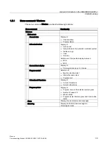
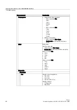
Страница 38: ...agement of part programs ASCII editor NC PLC and PROFIBUS diagnoses Logbook Menu bar The menu bar comprises the following menu commands File Edit Windows Display Context sensitive menu functions The functions that can be called using the menu commands File and Edit are context sensitive i e only those functions are offered that are possible in the context of the currently active window Example The...

Страница 39: ...inate system Distance to go Feed Override Switchover of the position display between MCS WCS Current block display Display of Part programs and up to 3 blocks Program control Selection of Machine function SBL1 SBL2 after each block Program test G functions H functions Display of Current G functions Current H functions Program pointer Display of Program name of the selected part program Number of p...

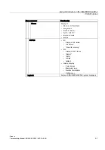
Страница 40: ...aste Load Unload Select Editing part programs Menu command File Open Double click the file with the left mouse button Editor Editing files Start the editor with Menu command File Open Double click the file with the left mouse button Menu command File Open Close Cut End Menu command Edit Copy Paste Load Unload Select Diagnostics PROFIBUS Bus Display of bus configuration Baud rate Cycle time Synchr ...

Страница 41: ...ality Slaves Display of Slave no DP address Assignment Active on the bus Synchr with NC Number of slots Details NC PLC NC Display of NC status NC Reset Clear NC memory PLC Display of PLC status RUN P RUN STOP MRES Latency display Current value Maximum value Number of violations Oscilloscope Logbook Display of SINUMERIK 840Di sl system messages ...

Страница 42: ...General Information on the SINUMERIK 840Di sl 1 5 840Di startup Manual 42 Commissioning Manual 05 2008 6FC5397 4CP10 4BA0 ...

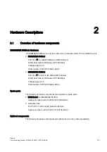
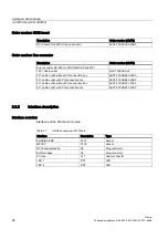
Страница 43: ...24 V Order number 6FC5 220 0AA31 2AA0 SINUMERIK 840Di sl PCU 50 3 P 2 0 GHz 1024 MB and MCI2 Board 40 GB hard disk and Windows XP ProEmbSys Voltage supply 24 V Order number 6FC5 220 0AA33 2AA0 Spare parts The following hardware components are available as spare parts MCI2 Board for SINUMERIK 840Di sl Spare part order number 6FC5 222 0AA02 2AA0 Hard disk drive For PCU 50 3 with support plate and da...

Страница 44: ...0S Order number 6FC5 203 0AF04 0AA0 OP 012 Order number 6FC5 203 0AF02 0AA1 OP 012T Order number 6FC5203 0AF06 1AA0 TP 012 Order number 6FC5203 0AF07 0AA0 OP 015 Order number 6FC5 203 0AF03 0AA0 TP 015A Order number 6FC5203 0AF08 0AA0 Components for distributed connection of SINUMERIK operator panel fronts TCU Thin Client Unit Order number 6FC5 312 0DA00 0AA0 Handheld units Handheld Terminal HT 8 ...

Страница 45: ...1 2EC31 SITOP POWER ACCUMODULE 24 V DC 10 A 3 2 AH Order number 6EP1 935 6MD11 PROFIBUS DP modules S7 I O modules SIMATIC ET 200 distributed peripheral system Detailed order information is given in References ST7 SIMATIC S7 programmable logic controllers Catalog ST 70 PP72 48 I O module Order number 6FC5 611 0CA01 0AA0 Interface modules ADI4 Analog Drive Interface for 4 Axes Order number 6FC5 211 ...

Страница 46: ...s SIMODRIVE 611 universal with options module Motion Control with PROFIBUS DP SIMODRIVE 611 universal E with options module Motion Control with PROFIBUS DP SIMODRIVE POSMO CD CA SIMODRIVE POSMO SI SIMODRIVE POSMO A For detailed ordering information on various drives see References BU SINUMERIK SIMODRIVE Order Document Catalog NC 60 ...

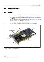
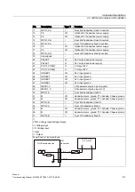
Страница 47: ...ith Motion Control Functionality X101 MPI Multi Point Interface or PROFIBUS DP without Motion Control Functionality X102 alternative MCI board extension slot variation Section MCI board extension slot version Page 56 The MCI board also provides the following functionality PLC Compatible with SIMATIC S7 CPU 317 2 DP Static memory SRAM for storing retentive NCK and PLC specific user data DFNXS EDWWH...

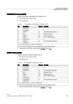
Страница 48: ... cable outlet without PG connection box 6ES7 972 0BA40 0XA0 35 cable outlet with PG connection box 6ES7 972 0BB40 0XA0 90 cable outlet without PG connection box 6ES7 972 0BA11 0XA0 90 cable outlet with PG connection box 6ES7 972 0BB11 0XA0 2 2 2 Interface description Interface overview Interfaces of the MCI board module Table 2 1 Interface overview MCI board Interface Description Type PROFIBUS DP ...

Страница 49: ...tput O Output B Bidirectional 2 in 5 and 6 are permissible only for supplying the bus terminating resistors Connection cable Refer to Subsection PCU50 Page 117 MPI DP interface X102 Interface description MPI DP interface X102 Connection 9 pin sub D socket Pin assignment Table 2 3 Pin assignment MPI interface X102 Pin Description Type 1 Function 1 Unassigned 2 Unassigned 3 RS MPI DP B RS 485 differ...

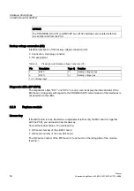
Страница 50: ... minus 2 BATT VI Backup voltage plus 1 VI Voltage input Diagnostic LEDs DP1 DP2 The diagnostics LEDs DP 1 und DP 2 are only used to display the internal status of the MCI board A diagnosis with regard to the PROFIBUS DP communication of the interfaces is not possible via the LEDs 2 2 3 Replace module License key If the MCI board is to be inserted as a replacement either only the MCI board or toget...

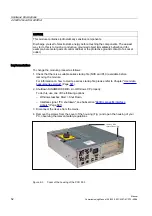
Страница 51: ...l equipment has parts and components that are at hazardous voltage levels Improper use of these devices can lead to death severe personal injury or substantial property damage Therefore when servicing the equipment you must follow all the instructions contained in this section and provided with the product Only qualified personnel should maintain this equipment Before starting any maintenance and ...

Страница 52: ...llows 1 Check that there is a suitable series startup file NCK and PLC available before removing the module For information on how to create a series startup file please refer to Chapter User data backup series startup Page 541 2 Shutdown SINUMERIK 840Di sl or Windows XP properly To do this use one of the following options Windows taskbar Start Shut Down Interface signal PC shutdown see Subsection...

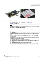
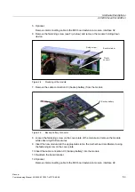
Страница 53: ...e module 7 Remove the cable connection X3 backup battery from the module DFNXS EDWWHU Figure 2 5 Backup battery connector 8 Loosen the fastening screw on the cover plate of the module and remove the module while observing ESD measures 9 Insert the new module into the appropriate slot on the mother board and fasten it using the fastening screw on the cover plate 10 Insert the cable connection X3 ba...

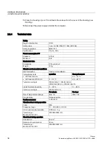
Страница 54: ... conditions Heat dissipation Open circuit ventilated Temperature limits operation Storage transport MCI board alone 40 70 C MCI board in PCU 50 3 5 55 C 20 60 C Tested according to DIN IEC 68 2 1 DIN IEC 68 2 2 DIN EN 60068 2 2 DIN IEC 68 2 14 Limits for relative humidity 5 80 5 95 Tested according to DIN IEC 68 2 30 Per minute Per hour Rate of temperature change Max 1 K Max 10 K Condensation Not ...

Страница 55: ...2 board for 840Di sl Manual Commissioning Manual 05 2008 6FC5397 4CP10 4BA0 55 Note The specified safety regulations certifications degree of protection and safety class only apply if the module is plugged into a SINUMERIK PCU 50 3 ...

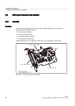
Страница 56: ...ot variant provides the following functions as an optional expansion board of the MCI board 4 binary inputs isolated 4 binary outputs isolated 2 measuring inputs isolated 2 handwheels non isolated Either differential or TTL handwheels switch S1 can be operated on the module DEOH GLVWULEXWRU 0 ERDUG H WHQVLRQ RFNLQJ VFUHZV HPDOH WKUHDG 81 6ZLWFK 6 3 EXV PHFKDQLFDO Figure 2 6 MCI board extension slo...

Страница 57: ... the de energized state Before you plug in or remove the cable distributor switch off the PCU shut down Windows XP correctly Otherwise short circuits might occur on the module This could destroy the module With switch S1 you can select the type of handwheel that is to be operated on the module Switch S1 Differential handwheels Switch S1 closed delivery state TTL handwheels Switch S1 open Different...

Страница 58: ... death severe personal injury or substantial property damage When servicing this device you should therefore observe all notices provided in this section and attached to the product itself Only qualified personnel should maintain this equipment Before starting any maintenance and service work disconnect the device from power supply Only spare parts approved by the manufacturer may be used Strictly...

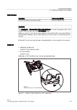
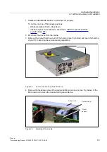
Страница 59: ...ecific interface signals Page 587 2 Disconnect the device from the mains 3 Remove the screws from the cover of the housing see Fig below and open the housing of your PC observing the relevant safety regulations Screws of the cover of housing Figure 2 8 Cover of the housing of the PCU 50 3 4 Remove the fastening screw of the module holding down device see Fig below of the MCI board and remove the m...

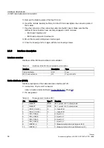
Страница 60: ...Interfaces of the MCI board extension slot variation Table 2 5 Interfaces of the MCI board extension slot variation Interface Description Type Cable distributor X121 Plug MCI board extension X4 Plug connector Cable distributor X121 Interface description of the cable distributor interface X121 Connectors 37 pin sub D connector refer to Section Cable distributor Cable Distributor Page 65 Pin assignm...

Страница 61: ...ON 3 O 4 Output 24 V 23 DOUT_CON 2 O 3 Output 24 V 24 GNDEXT VO 24 V input ground 25 GNDEXT VO 24 V input ground 26 GNDEXT VO 24 V input ground 27 GNDEXT VO 24 V input ground 28 MEPU1_S I 2 Measurement probe input signal 29 MEPU1_C I 2 Measurement probe input 0 V 30 MPG1_A I Input 2nd handwheel track A 31 M VO Handwheel vers ground TTL handwh Chassis ground 32 M VO Handwheel vers ground TTL handwh...

Страница 62: ...DLV 0 Digital inputs Electrical data of the digital input interface Isolated from the board electronics Common ground GNDEXT Digital outputs Electrical data of the digital output interface Isolated from the board electronics Common ground and with regard to the external power supply M24EXT Rated current 500 mA Differential handwheels Electrical data of the differential handwheel interface Connecte...

Страница 63: ...ther voltage areas board electronics digital inputs outputs and handwheels Signal delay active edge 10 μs Signal delay inactive edge 100 μs Note The maximum cable length is 25 m for all functions 2 3 4 Technical data Table 2 7 Technical data for MCI board extension slot version Safety Degree of protection IP 20 Safety class Safety class I in accordance with VDE 0106 P1 1982 IEC 536 Safety regulati...

Страница 64: ... to DIN IEC 68 2 30 Per minute Per hour Rate of temperature change Max 1 K Max 10 K Condensation Not permissible Quality assurance to ISO 9001 Vibrational load during operation Class 3M4 Frequency range 10 58 Hz 58 200 Hz Const excursion acceleration 0 075 mm 1g Tested as per module in PCU 50 3 DIN EN 60068 2 6 Shock load during operation Acceleration 50 m s2 Duration of nominal shock 30 ms Tested...

Страница 65: ...The cable distributor consists of a connector jacket for a 37 pin Sub D connector with enlarged interior The cable distributor is used to split the I O MPG extension interface X121 to a maximum of 7 single cables These must be connected in the order shown in Table Plug assignment To supply the digital outputs an external 24 V supply is possible at the cable distributor DEOH MMM DEOH MMM Figure 2 1...

Страница 66: ...e lower terminal bar and then secure the upper housing section This will reliably press the cable shields between the contact areas of the contact springs and contact them safely The shield potential is reliably routed to the housing of the PCU using the contact springs of the cable distributor on the front panel of the PCU Location of the interfaces DEOH QOHWV 7HUPLQDO FDSV RQWDFW VXUIDFHV 3OXJ L...

Страница 67: ...9 6 Supply for 4 binary outputs X10 7 bottom 1 Probe NOTICE When assembling the cable distributor make absolutely sure that the supplied insulating washer is installed correctly and the coding pins are installed Mounting The cable distributor is fastened using the two supplied adapter plates at the X121 cable distributor interface of the MCI board extension module using screws GDSWHU SODWH DEOH GL...

Страница 68: ...T M24EXT P24EXT X9 2 X9 1 X9 4 X9 3 6 41 0 rd or bn bk Shielding Supply of the 4 binary outputs of the MPI connector Chassis ground 24 V Chassis ground 24 V 3 22 4 23 OUTPUT 1 OUTPUT 3 OUTPUT 0 OUTPUT 2 X8 2 X8 1 X8 4 X8 3 5 41 0 rd or bn bk Shielding 4 binary outputs 2 Output 4 Output 1 Output 3 Output 5 24 6 25 7 26 8 27 INPUT 3 GNDEXT INPUT 2 GNDEXT INPUT 1 GNDEXT INPUT 0 GNDEXT X7 2 X7 1 X7 4 ...

Страница 69: ...1 1 X1 4 X1 3 1 21 0 rd or bn bk green yellow vt bu Shielding 1 Handwheel 6FC9320 5DB XA A 5 V 0 V 5 V 0 V XB B Signal names MPG0 1 5 V Voltage supply 1 2 handwheel 5 V MPG0 1 0 V Voltage supply 1 2 handwheel 0 V MPG0 1 A XA 1 2 differential handwheel input A XA MPG0 1 B XB 1 2 differential handwheel input B XB MEPUS 0 1 1 2 Measurement impulse signal MEPUC 0 1 1 2 Measuring impulse common ground ...

Страница 70: ...Hardware Descriptions 2 4 Cable distributor Manual 70 Commissioning Manual 05 2008 6FC5397 4CP10 4BA0 Colors rt Red or Orange br Brown bk Black gn Green ye Yellow vt Violet bu Blue ...

Страница 71: ...HQWDWLRQ ZLWK UHIHUHQFH WR RSHUDWLRQ ZLWK 23 L LQJ VFUHZV KRXVLQJ FRYHU WRS Figure 2 13 PCU 50 3 Perspective view with installed hard disk drive Order Number PCU as spare part with MCI board Description Order number MLFB with Windows XP ProEmbSys and MCI board PCU 50 3 C 1 5 GHz 512 MB SDRAM 6FC5 220 0AA31 2AA0 PCU 50 3 P 2 0 GHz 1024 MB SDRAM 6FC5 220 0AA33 2AA0 ...

Страница 72: ...cation to a large degree variable Screen resolution 640 x 480 up to max 1600 x 1200 Power supply DC 24V Interfaces to peripheral devices 1 x PROFIBUS DP max 12 Mbaud 1 x DVI I interface for external monitor 2 x Ethernet connections 10 100 Mbaud 1 x CF card shaft covered 4 x high speed USB ports USB 2 0 Interfaces to operator panel front LVDS panel interface channel 1 and optional channel 2 I O USB...

Страница 73: ...29 IP20 Certifications CE Electrical data Input voltage DC 24 V Max power consumption 1 x PCI slot length min 140 mm 1 x PCI slot length max 288 mm 3 3 V 5 V 12 V 12 V 2 A 2 A 0 3 A 0 05A Power consumption PCU PCI slot 1 Max 190 W 15 W Main power outage buffering time Min 20 ms Mechanical data Dimensions mm Width 297 Height 267 Depth 81 7 Weight approx 7 2 kg Mechanical ambient conditions with OP ...

Страница 74: ...standards DIN IEC 60068 2 1 DIN IEC 60068 2 2 2 14 Climate class 3K5 1K3 2K4 Temperature limits 9 W 2 5 55 C 14 W 2 5 50 C 24 W 2 5 45 C 20 60 C Rate of temperature change Max 10 K h Max 18 K h Limits for relative humidity 10 80 at 25 C 5 95 at 25 C Permissible change in the relative air humidity max 0 1 min 1 No slots may exceed this total power value 2 max power of additional extensions e g MCI ...

Страница 75: ...y with TCU Thin Client Unit via Ethernet In the following section the OP 012 operator front is described as an example in detail 2 6 1 Operator panel front OP 012 5HFDOO 0DFKLQH DUHD 6RIWNH V HWF NH UHD VZLWFKRYHU 0RXVH 86 IURQW LQWHUIDFH RQWURO NH JURXS XUVRU NH JURXS QXPHULFDO NH JURXS DOSKDEHWLF NH JURXS 6RIWNH V DQG GLUHFWNH V 6RIWNH V DQG GLUHFWNH V Figure 2 14 View of OP 012 operator panel f...

Страница 76: ...x 8 vertical rows of keys with softkey and direct control key function Direct keys connectable using PP031 MC or directly to the I Os Shift key for switchover to the second key level not for switching over the letters since they are uppercase only Integrated mouse Status LEDs for power supply and overtemperature USB interface at the front Degree of protection IP65 Can be combined with PCU or TCU E...

Страница 77: ...IK OP TP operator panel fronts and the SINUMERIK PCU The features include the following Communication with the PCU is performed via Industrial Ethernet 10 100 Mbaud in a separate sub network with DHCP server on the PCU Permits large distances between the PCU and operator panel front maximum possible distance between two network nodes access points approx 100 m Graphics resolutions 640x480 to 1024x...

Страница 78: ...g Manual 05 2008 6FC5397 4CP10 4BA0 References Comprehensive documentation about the configuration and commissioning of the TCU is given in Configuration BH Operator Components Manual Distributed configuration with TCU Startup IAM Commissioning Manual HMI Startup TCU IM5 ...

Страница 79: ...7 4CP10 4BA0 79 2 8 Handheld units 2 8 1 Handheld Terminal HT 8 Figure 2 16 Operator interface of the HT8 1 Emergency stop button 2 Handwheel 3 Rotary override switch 4 Protective collar 5 Display Touch screen 6 Function keys machine control panel 7 HMI control keys 8 Connecting cable ...

Страница 80: ...pable This allows trouble free connecting and disconnecting of the connector during operation without triggering an Emergency Stop The HT 8 is available in two variants with acknowledgement button Emergency Stop button override rotary switch with acknowledgement button Emergency Stop button rotary override switch and handwheel The module has the following essential features LC display as a Touch S...

Страница 81: ...n stop button 2 Rotary override switch 3 Display 4 Keyboard 5 Handwheel 6 Acknowledgement button left 7 Acknowledgement button right 8 Opening for the cable entry 9 Cable duct cover 10 Type plate 11 Standard position retaining magnet optional mounting bracket 12 Standard position mounting bracket optional Retaining magnet 13 Key operated switch Order Number Description Order number MLFB HT2 6FC5 3...

Страница 82: ...ns the HT2 is suitable for both right and left handed persons The magnetic handwheel allows intuitive axis feed motion All of the HT 2 keys can be freely configured and labeled The HT 2 can be mounted using a retaining magnet or an appropriate bracket Both the retaining magnet as well as the holder are available as accessory The module has the following essential features LC display black white Re...

Страница 83: ...P10 4BA0 83 2 9 Floppy disk drives 2 9 1 Floppy disk drive 3 5 USB Figure 2 18 External 3 5 floppy disk drive with USB interface Order Number Description Order number MLFB 3 5 disk drive with USB interface incl 1 m USB connecting cable 6FC5 235 0AA05 1AA2 Cover spare part 6FC5 247 0AA20 0AA0 ...

Страница 84: ... of 1 44 MB The disk drive has the following features USB interface Version 1 1 Can be inserted into customized operator panel fronts Bootable Input voltage 5 25 V DC Power consumption max 2 5 W Degree of protection acc to EN 60529 IP 54 at the front IP 00 rear side References For a complete description of the 3 5 floppy disk drive USB please refer to BH Operator Components Manual 3 5 disk drive U...

Страница 85: ...anual Commissioning Manual 05 2008 6FC5397 4CP10 4BA0 85 2 10 Power supply 2 10 1 SITOP POWER standard 24V 10A Figure 2 19 View SITOP POWER standard 24V 10A Order Number Description Order number MLFB SITOP POWER standard 24V 10A 6EP1 334 1SH01 ...

Страница 86: ...buffering 20 ms Rated power frequency 50 60 Hz Power frequency range 47 63 Hz Input current rated value 3 5 1 7 A Switch on current 25 C 55 A Output current rated value 24 VDC Output current tolerance 3 Efficiency 87 Output current rated value 10 A Electron short circuit protection with automatic restart Electrical isolation SELV to EN 60950 Safety class IEC 536 VDE 1006 T1 Class I Degree of prote...

Страница 87: ...oning Manual 05 2008 6FC5397 4CP10 4BA0 87 2 11 Uninterrupted power supply UPS 2 11 1 SITOP POWER DC UPS MODULE 15 86 LQWHUIDFH Figure 2 20 View SITOP POWER DC UPS MODULE 15 Order Number Description Order number MLFB SITOP POWER DC UPS module 15 USB interface 6EP1 931 2EC42 ...

Страница 88: ...lass III Degree of protection VDE 0470 IEC 529 IP 20 Setting options Connection threshold Charging current End of charge voltage Operating state ON OFF Backup time Interruption of output voltage Protection and monitoring functions Incorrect polarity protection Overcurrent and short circuit protection Exhaustive discharge protection Accu test Signaling of current status via LED Normal operation 85 ...

Страница 89: ...s however only performed at full speed corr to 12 Mbaud A commercial type four core shielded USB cable with a maximum cable length of 3 m can be used Table 2 12 Signal assignment of USB connector Pin Signal Description 1 VBUS Power supply 2 D Transmitted data 3 D Transmitted data 4 GRD Ground 2 11 2 SITOP POWER ACCUMODULE 24 V DC 10 A 3 2 AH Figure 2 21 View SITOP POWER lead acid battery module ...

Страница 90: ...OWER LEAD ACID MODULE 24 V DC 10 A 3 2 AH features the following It has two maintenance free closed lead acid batteries from the same lot which are installed in a holder and connected in series Complete with battery retainer and terminals Low self discharge rate of approximately 3 per month at 20 C Short circuit protection battery fuse 15 A 32 V Safety class IEC 536 VDE 1006 T1 Class III Degree of...

Страница 91: ...P10 4BA0 91 2 12 PP72 48 I O module 2 12 1 Assembly 6 VZLWFK IRU VHWWLQJ WKH 352 86 DGGUHVV 32 5 297 03 5 1 352 86 3RZHU 6XSSO LJLWDO LQSXWV RXWSXWV SLQ ULEERQ FDEOH FRQQHFWRU 21 2 Figure 2 22 PP72 48 I O module Order Number Description Order number MLFB PP72 48 I O module 6FC5 611 0CA01 0AA0 ...

Страница 92: ...48 digital outputs On board status display via four diagnostic LEDs To power the module and the digital outputs an external power supply source 24 V DC is required 2 12 2 Interface description Interface overview Interfaces of I O module PP72 48 Table 2 13 Interfaces of I O module PP72 48 Interface Description Type Power supply connection X1 Screw terminal block PROFIBUS DP X2 Socket PROFIBUS DP ad...

Страница 93: ...t Table 2 14 Pin assignment Ext power supply X1 Pin Description Type 1 Function 1 P24 VI External supply for module 24V 2 M24 VI Reference for external supply 3 PI VI Protective conductor of the external supply 1 VI Voltage input Connecting cable The required connecting cables must be provided by the user Wire conductor cross section 1 0 1 5 mm2 AWG17 AWG16 Power supply For data regarding the supp...

Страница 94: ...d 5 DGND VO Data reference potential M5V 6 VP VO Supply voltage plus P5V 7 8 RxD TxD N B Receive transmit data N A line 9 1 VO Voltage output O Output B Bidirectional Plug 6ES7972 0BA40 0XA0 cable outlet 350 without PC socket connector 6ES7972 0BB40 0XA0 cable outlet 350 with PC socket connector 6ES7972 0BA11 0XA0 cable outlet 900 without PG socket connector 6ES7972 0BB11 0XA0 cable outlet 900 wit...

Страница 95: ... after power OFF ON Digital inputs outputs X111 X222 X333 Interface description of the digital input output interfaces X111 X222 X333 Connectors 50 pin ribbon cable connector Pin assignment on each connector Table 2 17 Pin assignment X111 X222 X333 Pin Signal designation Type 1 Pin Signal designation Type 1 1 M VO 26 Input 2 7 I 2 P24OUT VO 27 3 Input 0 0 I 28 4 Input 0 1 I 29 5 Input 0 2 I 30 6 I...

Страница 96: ... Input 2 3 I 47 DOCOMx VI 23 Input 2 4 I 48 DOCOMx VI 24 Input 2 5 I 49 DOCOMx VI 25 Input 2 6 I 50 DOCOMx VI 1 VI Voltage input VO Voltage output I Signal Input O Signal output x with x 1 2 3 Digital inputs Terminal assignment for the digital inputs The following figure shows an example of the terminal assignment for the digital inputs on connector X111 Connectors X222 and X333 are assigned analo...

Страница 97: ...ge 100 Connection cable The required connecting cables ribbon cables must be provided by the user Electrical specification of the digital inputs Table 2 18 Electrical specification of the digital inputs Digital inputs min Standard Max Nominal Voltage at high signal level UH 15 V 1 30 V 24 V Input current IIN at VH 2 mA 15 mA Voltage at low signal level UL 30 V 5 V 0 V Signal delay time TPHL 2 0 5 ...

Страница 98: ...rce must be connected to X111 X222 X333 Pin 1 M For further data see Subsection Power Supply Page 100 CAUTION It is the user s responsibility to ensure that the max current consumption per DOCOMx pin X111 X222 X333 Pins 47 48 49 50 does not exceed 1 A The power supply 24 V DC for the digital outputs must therefore be connected to all 4 pins X111 X222 X333 Pin 47 48 49 50 for each DOCOMx Electrical...

Страница 99: ...cation cycle time must be taken into account Incorrect connection causes neither high level nor destruction of the outputs General electrical properties No electrical isolation Current limitation to maximum 500 mA Protection against short circuit overtemperature and loss of ground Automatic disconnection in case of undervoltage LED Status display The module has 3 LEDs through which the module stat...

Страница 100: ...T then remains open Specification of the supply voltages 24V DC The external power supply voltages must be generated as functional extra low voltages with safe electrical isolation according to IEC 204 1 PELV and must be grounded centrally by the user The reference ground of the terminals X111 X222 X333 pin 1 GND must be connected to a common grounding point with the reference ground of the power ...

Страница 101: ...sumption Maximum Approx 40 W On the module side the power supplies must be protected against Polarity reversal Short circuit elec current limitation of the outputs Overload fuse protection 2 12 4 Grounding The module must be installed according to EN 60204 If a large area permanent metallic connection with the central ground point through the rear panel is not possible the mounting plate must be c...

Страница 102: ...Hardware Descriptions 2 12 PP72 48 I O module Manual 102 Commissioning Manual 05 2008 6FC5397 4CP10 4BA0 2 12 5 Dimension drawing 6 0 16 Figure 2 25 Dimension drawing PP72 48 I O module ...

Страница 103: ...UL CSA CE Power consumption At nominal load 11W Mechanical data Dimensions WxHxD mm 194 x 325 x 35 Weight approx 0 3 kg without mounting plate approx 1 2 kg with mounting plate Climatic environmental conditions Heat dissipation Open circuit ventilated operation Storage transport Temperature limits 0 50 C 20 55 C 40 70 C Limits for relative humidity 5 95 Without condensation 5 95 Without condensati...

Страница 104: ...HWWLQJ WKH 352 86 DGGUHVV DQDORJ VHWSRLQW RXWSXWV s 9 LV HQFRGHU FRQQHFWLRQ IRU D LV HQFRGHU FRQQHFWLRQ IRU D LV FRQQHFWLRQ IRU GLJLWDO RXWSXW VLJQDOV RQQHFWLRQ IRU SURWHFWLYH JURXQG VFUHZ 0 LDJQRVWLF ಫV 3 703 5 FRQQHFWLRQ IRU GLJLWDO LQSXW VLJQDOV HQFRGHU FRQQHFWLRQ IRU D LV HQFRGHU FRQQHFWLRQ IRU D LV FRUU WR 352 86 DGGUHVV 21 2 Figure 2 26 Connection overview for ADI4 Order Number Description O...

Страница 105: ...and drive specific digital input output signals On board status display via four diagnostic LEDs To power the module and the digital outputs an external power supply source 24 V DC is required NOTICE Please observe the following framework conditions for operating the ADI4 DP slave An ADI4 DP slave can only be operated on an equidistant PROFIBUS DP see Subsection DP Slave ADI4 Page 286 An ADI4 DP s...

Страница 106: ...nual 106 Commissioning Manual 05 2008 6FC5397 4CP10 4BA0 2 14 Diagnostic repeater for PROFIBUS DP 2 14 1 Assembly Figure 2 27 View Diagnostics Repeater for PROFIBUS DP Order Number Description Order number MLFB Diagnostic repeater for PROFIBUS DP 6ES7 972 0AB01 0XA0 ...

Страница 107: ...es 1 5 Mbaud 2 5 TBIT 153 ns 12 MBaud TBIT 83 3 ns Jitter 1T 1 48 MHz 20 83 ns Monitoring function of isosynchronous PROFIBUS DP bus cycle TDP min 1 ms max 32 ms Tolerance range TDP monitoring 2 μs Tolerance range TDX monitoring 10 μs Supply voltage Rated voltage 24 V DC 20 4 to 28 8 V Permissible ambient conditions Operating temperature 0 C to 60 C Transportation storage temperature 40 C to 70 C ...

Страница 108: ...Hardware Descriptions 2 14 Diagnostic repeater for PROFIBUS DP Manual 108 Commissioning Manual 05 2008 6FC5397 4CP10 4BA0 ...
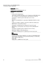
Страница 109: ...h panels 3 8 23 7 23 23 23 23 6 23 73 73 3RVVLEOH FRQILJXUDWLRQV FHQWUDOL HG FRQILJXUDWLRQ RQQHFWLRQ RI WKH 23 73 GLUHFWO WR WKH 3 8 GLVWULEXWHG FRQILJXUDWLRQ RQQHFWLRQ RI WKH 23 73 WR D 7 8 7KLQ OLHQW 8QLW RPPXQLFDWLRQ ZLWK WKH 3 8 YLD WKHUQHW Figure 3 1 System overview of SINUMERIK 840Di sl Operator panels and touch panels ...

Страница 110: ...RI WKH 1 FDQ EH RSHUDWHG YLD WKLV 352 86 OLQH LDJQRVH 5HSHDWHU IRU 352 86 3 3 3 6 0 7 32 5 3 PDFKLQH FRQWURO SDQHO 0 3 PDFKLQH FRQWURO SDQHO 0 3 6 1 0 6 6 6 02 5 9 XQLYHUVDO RSWLRQ PRGXOH 0RWLRQ RQWURO ZLWK 352 86 3 OWHUQDWLYH 6 180 5 L VO 3 8 0 RDUG 352 86 3 352 86 3 HFHQWU 2 V VWHP 6 0 7 7 3XVKEXWWRQ 3DQHO 033 2 0RGXO 33 0 1 8 Figure 3 2 System overview of SINUMERIK 840Di sl PROFIBUS DP schemati...

Страница 111: ...BA0 111 3 1 3 PCU components SIEMENS SIEMENS 0RXVH H ERDUG 4 57 ORSS GULYH ಯ 5RP ULYH 6 723 32 5 VWDQGDUG 9 6 723 869 0RGXOH ZLWK 6 723 32 57 OHDG DFLG PRGXOH 2SWLRQDOO 0RQLWRU 3 3 6 0 7 32 5 3 QGXVWULDO 3 3 8 Figure 3 3 System overview of SINUMERIK 840Di sl PCU components as a diagram ...

Страница 112: ...QWHUIDFH 7KHUHIRUH QR GULYHV DQG QR 2V RI WKH 1 FDQ EH RSHUDWHG YLD WKLV 352 86 OLQH 0 ERDUG 6 1 0 6 6 2WKHUZLVH 6 02 5 9 XQLYHUVDO ZLWK RSWLRQ PRGXOH 0RWLRQ RQWURO ZLWK 352 86b 3 3XVKEXWWRQ SDQHO 033 0DFKLQH FRQWURO SDQHO 0 3 0DFKLQH FRQWURO SDQHO 0 3 3 3 H J 6 0 7 3RZHU 3 2 0RGXOH 33 6 0 7 3 7 LDJQRVWLF UHSHDWHUV RU 352 86b 3 Figure 3 4 SINUMERIK 840Di sl MCI board and PROFIBUS DP components ...

Страница 113: ...3 Note For details on general accessories such cables connectors and prefabricated cables please refer to References Catalog NC 61 MOTION CONNECT 3 2 2 MCI board extension 0 ERDUG H WHQVLRQ DEOH GLVWULEXWRU SUREH DQGZKHHO GLJLW QSXW GLJLW 2XWSXW Figure 3 5 SINUMERIK 840Disl MCI board extension ...

Страница 114: ... 3 3 H J 6 0 7 3RZHU 3 H W 520 ULYH H ERDUG 4 57 H W 2SHUDWRU 3DQHO 23 YLD 7KLQ OLHQW 8QLW 7 8 RPSDQ QHWZRUN 6 VWHP QHWZRUN 6 723 32 5 ZLWK 6 723 836 PRGXOH DQG 6 723 32 5 OHDG DFLG EDWWHU PRGXOH Figure 3 6 SINUMERIK 840Di sl PCU 50 3 right housing 2 LQWHUIDFH IRU FRQQHFWLQJ WKH 2 FDEOH RI WKH RSHUDWRU SDQHO IURQW 2SWLRQDO FRQQHFWLRQ IRU RSHUDWRU SDQHO IURQW ZLWK 86 IURQW LQWHUIDFH 9 6 LQWHUIDFH I...

Страница 115: ...NLW OHFWURQLF KDQGZKHHO OHFWURQLF KDQGZKHHO 0 5 1 6723 HQDEOLQJ FLUFXLW 3 LQSXWV 352 86 3 GLDJQRVWLF UHSHDWHU PDFKLQH FRQWURO SDQHO 0 3 0 3 3XVKEXWWRQ 3DQHO 033 GULYH 6 1 0 6 6 YLD 8 6 0 7 7 3 2 PRGXOH 33 DEOH GLVWULEXWRU 0 ERDUG H WHQVLRQ 6ORW YDULDQW 2SWLRQ 6 180 5 L VO 3 8 352 86 0DVWHU RU 6ODYH 2 0 RDUG 352 86 0DVWHU GULYHV 2 352 86 3 0 DXG P FDEHO ഋഋ ื P IRU KDQGZKHHO VLJQDOV FDEHO ഋഋ ื P IRU...

Страница 116: ...let 350 with PC socket connector 6ES7972 0BB12 0XA0 cable outlet 900 with PG socket connector Cables 6XV1830 0EH10 by the meter non trailable 6XV1830 3EH10 by the meter trailable 4 The cable is included in the scope of supply for an overview of the standard PC interfaces see Section PCU 50 3 Page 114 as well as References BH Operator components Manual Component PCU 50 3 5 Cables 6FX8002 2CP00 1A 0...

Страница 117: ...3 3 2 PCU50 6 180 5 RSHUDWRU SDQHO IURQW HOHFWURQLF KDQGZKHHO Y P QGXVWULDO WKHUQHW PDFKLQH FRQWURO SDQHO 0 3 6 180 5 7KLQ OLHQW 8QLW 7 8 6 180 5 RSHUDWRU SDQHO IURQW WKHUQHW WKHUQHW 9 6 2 6 180 5 L VO 3 8 Figure 3 9 Connection overview PCU 1 The cable is included in the scope of supply 2 Cables 6FX8002 2CP00 1A 0 3 For information on Ethernet cables please refer to References Catalog NC 61 MOTION...

Страница 118: ...Configuration 3 3 Connection overview Manual 118 Commissioning Manual 05 2008 6FC5397 4CP10 4BA0 ...
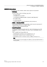
Страница 119: ...trol via an equipotential bonding cable Rules for routing cables In order to achieve the best possible noise immunity for the complete system control power section machine the following EMC measures must be observed Signal cables and load cables must be routed at the greatest possible distance from one another Only use SIEMENS signal cables for connecting to and from the NC or PLC Signal cables ma...

Страница 120: ... printed conductors Personnel may only touch components if you are permanently grounded by means of an antistatic chain you are wearing ESD boots or ESD boots with grounding strips in conjunction with ESD flooring Boards modules must only be placed on conductive surfaces table with ESDS surface conductive ESDS foam ESDS packaging ESDS transport container NOTICE Modules with their own voltage sourc...

Страница 121: ...e grounded and connected to shields The load capacity of the central power supply is taken into account Drives Additional points should be observed depending on the drive system used For detailed information please refer to SINAMICS S120 Commissioning Manual Section Prerequisites for startup SIMODRIVE 611 universal FBU Function Manual SIMODRIVE 611 universal Section General information on startup ...

Страница 122: ...uide for the SINUMERIK 840D sl machine configuring SIMODRIVE 611 universal converter system Motors SIMATIC S7 I O components HMI user interfaces Note Guidelines for machine configuration The device manual Guidelines for machine configuration SINUMERIK 840D sl currently refers only to SINUMERIK 840D sl with SINAMICS S120 The information contained in this can in principle be applied to SINUMERIK 840...

Страница 123: ... commissioning of the NC channels axes and spindles etc Section Axes and spindles Page 385 5 Set up the alarm texts Section Alarm and message texts Page 493 6 Perform the commissioning of the drives SINAMICS S120 Section Drive commissioning SINAMICS Page 307 SIMODRIVE 611 universal Section Drive commissioning SIMODRIVE Page 345 7 Carry out a dry run for all axes and the spindle Section 840Di sl sp...

Страница 124: ... be pending The displayed axes of the NC can be traversed by simulation Factory settings The hard disk of the PCU is already partitioned upon delivery for operating the SINUMERIK 840Di sl Additional software applications which have been been ordered e g HMI Advanced are ready for installation under D Setup Apps Application1 Application n 1DPH 0 5 1 RQWHQW LQ3 1DPH 6 67 0 RQWHQW LQGRZV 3 1DPH 703 R...

Страница 125: ... REBOOT None of the listed applications are installed and you are taken to the Windows desktop The installation menu is displayed again the next time the PCU is booted CANCEL installation None of the listed applications are installed Application Subsequent installation of a hard drive image as part of a standard commissioning NOTICE The current installation menu will not be displayed the next time...

Страница 126: ...40dismp PROFIBUS MCP 840disl_tb version _DPMCP arc Ethernet MCP 840disl_tb version _ETHMCP arc Ethernet MCP and HT 8 840disl_tb version _ETHMCP_HT8 arc Proceed as follows for loading the series commissioning file 1 Start the SinuCom NC commissioning tool from the Windows taskbar Start Programs SinuCom NC SinuCom NC 2 Use SinuCom NC to load the series startup file PLC_SMP ARC into the PLC Menu comm...

Страница 127: ...erial number MCI board SRAM MCI board OK SRAM image hard disk OK SRAM backup hard disk OK Used user data remark Known yes Not applicable Not applicable MCI Normal power up Known No yes Not applicable IMAGE no message box or alarms See Section Power up after changing the MCI boards case 1 Known No No yes BACKUP message box and alarm See Section Power up after changing the MCI boards case 2 Known No...

Страница 128: ...board is OK the system does not request which SRAM MCI or IMAGE is to be used when booted for the first time SW update The SRAM of the MCI board is always used SRAM image or SRAM backup hard disk OK Yes The following criteria must be fulfilled The NC and PLC software version of the SRAM image backup must match the installed software version Windows XP must have been shut down correctly the POWER F...

Страница 129: ...s XP is not correctly shut down before changing the backup battery an inversion of the SRAM memory cells during the battery change cannot reliably be detected The SINUMERIK 840Di sl must then be recommissioned 5 3 3 Startup after replacement of the MCI board After the MCI board has been replaced the subsequent procedure depends on the previous history There is a distinction between the following s...

Страница 130: ... SRAM image Case 2 An up to date SRAM image does not exist A fault occurred with the MCI board during operation of the SINUMERIK 840Di sl Windows XP has possibly been shut down correctly but no SRAM image could be created After replacement based on the hardware serial number the MCI board will be identified as unknown Since no up to date SRAM image exists the SRAM backup is written back into the S...

Страница 131: ... Page 486 5 3 4 Power up after reinstallation update of the 840Di sl software If the 840Di sl software is reinstalled on an operational SINUMERIK 840Di sl the user data saved in the SRAM of the MCI board is retained To achieve this it is essential that the current NC and PLC software version complies with the software version with which the battery backed user data of the SRAM have been created Th...

Страница 132: ...n can be made Responses The user must decide through the following message box which user data are to be used further 6 180 5 L VO 1 3 1HZ 0 FDUG GHWHFWHG 9DOLG XVHU GDWD DUH IRXQG RQ 0 FDUG RQ KDUGGLVN I RX ZDQW WR XVH WKH XVHU GDWD IURP 0 FDUG SUHVV ಯ HVಯ I RX ZDQW WR XVH WKH XVHU GDWD IURP WKH KDUGGLVN SUHVV ಯ1Rಯ HV 1R 5 3 6 Startup after importing a backup copy If a backup copy Ghost image of ...

Страница 133: ...ower Fail is only guaranteed if the PCU is operated within its defined specifications References BH Operator components Manual Section Component PCU 50 Case 2 SRAM not backed up If the SINUMERIK 840Di sl was operated outside its defined specifications it may not be possible to save the user data in the SRAM Proceed therefore as in section Power up after changing the MCI board Page 132 Case 2 descr...

Страница 134: ... system response ensures that an error in the protection circuit of the MCI board extension module or in the configuration of the shutdown signal does not result in an endless loop power up shutdown signal power up etc As long as the message box has not been acknowledged the protective circuit of the MCI board extension module and the configuration of the shutdown signal see Section Menu Settings ...

Страница 135: ...nctions 5 4 1 Activating Proceed as follows to enable the Service Desktop 1 As soon as 1 is displayed under the version number on the bottom right of the startup screen press the key 3 9 1 Figure 5 2 Display during startup of the SINUMERIK 840Di sl 2 Enter a password for protection levels 0 2 Protection level Password Area 0 Reserved Siemens 1 SUNRISE default Machine manufacturer 2 EVENING default...

Страница 136: ...ed to the PCU directly References Equipment Manual Operator components and Networking Chapter PCU 50 3 Commissioning Calibration of the touchscreen System Network Center Setting up the Ethernet connection of a TCU to the SINUMERIK 840Di sl References Equipment Manual Operator components and Networking Chapter Networking Commission system network PCU System Network Center SNC HMI Analyzer Analysis ...

Страница 137: ...f an HT8 machine control panel signal References Equipment Manual Operator components and Networking Chapter Networking Install Deinstall MCIS RCS Host Installation and uninstall program of the host for remote diagnostics of SINUMERIK systems with Windows based HMI within the framework of the Motion Control Information System References Catalog NC 61 Motion Control Information System MCIS Folder S...

Страница 138: ... screen system information is written to the following file D Memory dmp 5 4 5 Starting OEM programs OEM directories OEM programs can be executed before starting the SINUMERIK system software These programs or their respective links must be stored in the following directories C RunOEM SeqOnce Programs stored here are started once and sequentially C RunOEM Seq Programs stored here are started on ev...

Страница 139: ...plorer 5 4 6 User specific HMI startup images User specific startup images can be displayed while the HMI is booting The boot images must be stored in bitmap format BMP in a defined directory structure Directory structure The directory structure must be created under F OEM IB DATA according to the following schema F OEM IB DATA NCK Type screen resolution file name BMP Parameters NCK type The diffe...

Страница 140: ...ame You can choose any file name 5 4 7 HMI Explorer The HMI Explorer is used to manage the Siemens A D software components on the PCU The following main functions are available Version display Installation de installation and re installation Application specific information detailed information history available language versions etc Installation directory 9 9 9 9 9 5 9 9 9 9 9 9 9 5 9 9 0 DVH DVH...

Страница 141: ...n Version number with which the product was first installed Installation directory The path of the installation directory of a software component is displayed in the Install dialog box Menu command Install 5 4 8 SW installation update The Service Desktop allows you to install or update software directly from an external computer using a specially configured network link For a detailed description ...

Страница 142: ...a Power Off On 2 While starting up the PCU press the key Cursor Down in the selection image for the operting system to be started The selection screen is displayed immediately after the booting of the PCU 26 RDGHU 3OHDVH VHOHFW WKH RSHUDWLQJ V VWHP WR VWDUW 6 180 5 6HUYLFH HVNWRS QRW YLVLEOH 8VH DQG ൻ WR PRYH WKH KLJKOLJKW WR RXU FKRLFH 3UHVV QWHU WR FKRRVH 3 Enter a password for protection levels...

Страница 143: ...L 1 3 I RX ZDQW WR FKDQJH 1 3 VWDUWXS PRGH VHOHFW ZDQWHG PRGH DQG SUHVV 2 6WDUW 1 3 R QRW VWDUW 1 3 6WDUW 1 3 ZLWK PRGLILHG VZLWFK VHWWLQJV 1 VZLWFK 1RUPDO 3 VZLWFK 6723 5813 581 6723 05 6 FRQILUP LQ 0 Figure 5 4 Start with PLC in the STOP mode example NC modes The following NCK modes can be set Normal Loading standard machine data After startup the NC is in the reset state All machine and user da...

Страница 144: ... performed by the PLC 1 The PLC disconnects all links 2 The user data are deleted data and program blocks 3 The system data blocks SDB are deleted 4 Battery backed data are copied back into the RAM area from the PLC after general reset 5 The diagnostics buffer the MPI parameters the clock time and the operating hours counter are not reset Note After startup in the specified mode the PLC must be ex...

Страница 145: ... the local network connection Windows Taskbar Start Settings Network Connections Local Area Connections with respect to the IP addresses and the domains are given as follows Dialog Local Area Connections Properties Tab General IP address via DHCP Option Obtain an IP address automatically Automatic DNS server address Option Obtain a DNS server address automatically Tab Alternate Configuration Autom...

Страница 146: ...poses The control will then cyclically display a reminder alarm that a license has not yet been registered for the option The procedure for ordering through to entering the license key of an option is as follows 1 Order and purchase of the relevant license packages and or single licenses Order catalog NC 61 2 Activate the options SinuCom NC 3 Obtain the license key for the required control Web Lic...

Страница 147: ...QV 7UDFH 6HWXS L DUG 352 86 DVVLJQPHQW KDQQHO PRGHJURXS DVVLJQPHQW LV FRQILJXUDWLRQ LV 5 5 5 5 5 XQFWLRQV Input fields Options Button License Key LOH GLWLQJ 7DUJHV V VW LDJQRVLV 7RROV 9LHZ LQGRZ 6LQX RP 1 2QOLQH 6LQX RPB1 B3URMHFW 0 EORFN ODUP ORJ Current License Key is not sufficient Get a new License Key Options MD Block1 Option Show all Show only not licensed NCU SW 31A with HMI Embedded 6FC584...

Страница 148: ...Power On and Power Up 5 7 License management Manual 148 Commissioning Manual 05 2008 6FC5397 4CP10 4BA0 ...
Страница 149: ...the PLC PLC317 2DP 6FC5 317 2AJ10 0AB0 Memory for PLC basic program and user program 768 KB Data block memory Max 256 KB Memory submodule No Bit memories 32768 Timers 512 Counter 512 Clock memory 8 Program and data blocks OB 1 10 20 21 32 35 40 55 57 80 82 85 87 100 121 122 FB 0 2048 FC 0 2048 DB 1 2048 Max length of data block 32 KB Max block length FC FB 64 KB Inputs outputs addressing capacity ...

Страница 150: ...munication Yes Consistent data to standard slave via SFC 14 15 128 6 1 3 PLC program The PLC program is constructed modularly It comprises the two parts PLC basic program The PLC basic program organizes the exchange of signals and data between the PLC user program and the NCK HMI and machine control panel components The PLC basic program is part of the PLC Toolbox supplied with SINUMERIK 840Di sl ...

Страница 151: ...ystem software are two STEP 7 projects on which the basic configuration of the SINUMERIK 840Di sl Station and an MCP PROFIBUS Ethernet is displayed The example projects can be used as a basis for your own projects Storage path The example projects are on the SINUMERIK 840Di sl CD under Example project with PROFIBUS MCP CD path support 840dismp 840Di_sl_DPMCP_smpl zip Example project with Ethernet ...

Страница 152: ...0Di sl PLC via one of the Ethernet interfaces of the PCU Ethernet 1 company network or Ethernet 2 Local network Configuring the PG PC interface is described in Section Commissioning Page 155 Configuring the communication processor CP 840D sl of the SINUMERIK 840Di sl is described in the Subsection Parameterizing the communication processor CP 840D sl Ethernet Page 170 Internal connection A local S...

Страница 153: ... cyclic processing OB40 process alarm 2 2 2 RQO UHTXLUHG LI D 0 3 RU 03 EXV LV FRQQHFWHG 5HVWDUW 6WDUW XS H J 8 SDUDPHWHUV 8VHU 3URJUDP FOLF 3URFHVVLQJ 0 3B 17 3 2 1 0RGH URXS KDQQHO LV 6SLQGOH 0 3 8 70 8VHU SURJUDP 68 FRQ LV 6SLQGOHV 70 70B7UDQV 70B LU 9DU UHDG ZULWH 3 6HUYLFHV 6WDU HOWD UURU DQG RSHUDWLRQDO PHVVDJHV GLVSOD FRQWU JURXS GLVWULEXWRU 3B35 8VHU SURJUDP 3URFHVV DODUP 0 3 0 3B 0 0 3B 7...

Страница 154: ... can be processed in the SIMATIC manager Select the appropriate block e g OB 100 in the folder blocks of the corresponding module Use the menu command Edit Open Object to open the block or double click the block with the left mouse button Processing the blocks in the KOP AWL FUP Editor Switching the block view via the menu command View KOP or AWL or FUP ...

Страница 155: ...ERIK 840Di sl must be successfully booted to commission the PLC NCK in the cyclic operation PLC in the status RUN Note The NCK and PLC status can be checked with User interface 840Di startup See corresponding online help Commissioning tool SinuCom NC See corresponding online help User interface HMI Advanced option See Section NC PLC Diagnostics Page 486 SIMATIC STEP 7 SIMATIC STEP 7 is required in...

Страница 156: ...C interface parameters can be checked and set in the SIMATIC Manager via menu item Options Set PG PC interface Dialog Set PG PC interface Tab Access path Interface parameterization used Interface OK NOTICE Do not select ISO interfaces as Ethernet interfaces from the list of interfaces e g ISO Ind Ethernet Realtek RTL8139 Instead use the appropriate TCP IP interfaces e g TCP IP Realtek RTL8139 6 2 ...

Страница 157: ...d option 840Di startup Start 840Di startup Windows XP taskbar Start Programs SINUMERIK 840Di 840Di Startup Open the dialog box Menu command Window Diagnosis NC PLC HMI Advanced option Open the dialog box Operating area switchover Start up NC PLC Diagnosis Request general reset of PLC PLC Delete Program After general reset the PLC is in RUN mode i e the LED RUN in the display is green 6 2 5 First c...

Страница 158: ...Proceed as follows in the dialog boxes 1 PLC general reset Group PLC Button PLC Delete Program NOTICE After a general reset of the PLC interface X102 MPI DP of the MCI board is set to MPI and the following MPI parameters are set MPI address of the PLC 2 MPI data transmission rate 187 5 kbaud 2 Delete NC data Group NC Button NCK Default Data 3 Initiate NC Reset To start cyclic operation or NC PLC c...

Страница 159: ...97 4CP10 4BA0 159 Note Since no PLC program is executed after PLC general reset the following alarms are displayed Alarm 120201 Communication failed Alarm 380040 PROFIBUS DP Configuring error 3 parameter Alarm 2001 PLC not booted These alarms have no influence on how to continue ...

Страница 160: ...101 PROFIBUS DP In the case of the SINUMERIK 840Di sl the position controller cycle of the NC is derived directly from the isochronous PROFIBUS cycle Defined values must therefore always be entered for the following PROFIBUS parameters Mode DP master Isochronous PROFIBUS Active Isochronous time TDP on PROFIBUS DP Position controller cycle clock Both the PLC and the NC have direct access to this PR...

Страница 161: ...ucture 6 3 2 Inserting Station 300 Before you can insert the required hardware in the S7 project you must first insert a SIMATIC Station 300 in the project Select the menu command Insert Station SIMATIC Station 300 6 1 6 0 7 0DQDJHU 6 1 L VO 6 1 L VO LQVWDOODWLRQ SDWK VWHS V SURM 6 1 L VO 6WDWLRQ GLW QVHUW 7DUJHW 6 VWHP 9LHZ 7RROV LQGRZ HOS QR LOWHU XW WUO RS 3DVWH HOHWH QVHW QHZ REMHFW 3 5HQDPH 2...

Страница 162: ...4BA0 Starting HW Config Start HW Config by opening the station and double clicking the hardware icon 6 1 L VO QVWDOODWLRQ SDWK VWHS V SURM 6 1 L VO 6LQ L VO 6 0 7 DUGZDUH Figure 6 3 Inserting the SIMATIC 300 station We recommend giving the inserted SIMATIC Station 300 a meaningful name for example 840Di sl ...

Страница 163: ...ILJXUDWLRQ 6 1 L VO 6WDWLRQ GLW QVHUW 7DUJHW 6 VWHP 9LHZ 7RROV LQGRZ HOS 6WDWLRQV ZLQGRZ VWDWLRQ VWUXFWXUH 6WDWLRQV ZLQGRZ HWDLOHG YLHZ DUGZDUH FDWDORJ 352 86 3 352 86 3 352 1 7 2 6 0 7 6 0 7 6 0 7 3 DVHG FRQWURO 6 0 7 3 6WDWLRQ GHIDXOW 6ORW HVLJQDWLRQ Figure 6 4 HW Config Names of the main areas Note To check whether a module selected from the hardware catalog complies with the module in the auto...

Страница 164: ...P for Industrial Ethernet TCP IP Default designation CP 840D sl Inserting the 840Di sl Rack The 840Di sl Rack is located in the hardware catalog under Profile Standard SIMATIC 300 SINUMERIK 840Di sl 840Di sl Right click to select the 840Di sl Rack and drag it to the Station window while holding down the mouse button When you release the mouse button the 840Di sl Rack will be inserted in the S7 pro...

Страница 165: ...ault setting of the PROFIBUS address is 2 It is recommended to retain this setting Subnet Equidistant DP cycle Equidistant time Equidistant time The set equidistant DP cycleis accepted in case of SINUMERIK 840Di sl as NC system clock cycle and position controller cycle Position controller cycle NC system clock cycle equidistant DP cycle The time you can set for the equidistant DP cycle depends on ...

Страница 166: ...uidistant Active equidistant bus cycle Equidistant DP cycle Equidistant time OK OK OK Note S7 Subnetz ID S7 subnet ID It is recommended to note the S7 Subnetz ID S7 subnet ID because it will be needed later for parameterization of the routing settings SINAMICS See Section Create new project without Project Wizard Page 310 SIMODRIVE See Section Setting the routing information Page 351 ...

Страница 167: ...LJ 6 180 5 RQILJXUDWLRQ 6LQ L VO 6WDWLRQ GLW QVHUW 7DUJHW 6 VWHP 9LHZ 7RROV LQGRZ HOS 352 86 3 PDVWHU V VWHP 3 3 03 3 3 1 VO 3 VO L VO L VO 3 3 9 03 3 3 1 VO 3 VO 9 6ORW 0RGXOH 2UGHU 1XPEHU L 0 L VO 3 3B 6 180 5 L VO 352 86 3 352 86 3 352 1 7 2 6 0 7 3 38 0 0 0 7 16 21 1 7 5 1 36 5 60 6 180 5 L VO L VO HIDXOW Figure 6 6 HW Config SINUMERIK 840Di sl Rack To parameterize the PROFIBUS interface X102 ...

Страница 168: ...operties PROFIBUS interface MPI DP Tab Parameter address Address Button New Dialog Properties New Subnet PROFIBUS Tab Network settings Data transfer rate Data transfer rate Profile DP OK Tab Mode Radio button Mode OK OK NOTICE If the interface X102 is not networked with PROFIBUS then it must at least be networked with MPI in order to enable the internal communication via SOFTMC See Subsection Para...

Страница 169: ...OFIBUS interface X101 Page 165 the 840Di sl Rack is displayed in the Station window To parameterize the MPI interface you will have to make the following parameter settings Interface type Transmission rate By double clicking the module MPI DP slot X1 in the 840Di sl rack open the properties dialog of MPI DP Dialog Dialog MPI DP Properties Tab General Group Interface Type MPI Button Properties Dial...

Страница 170: ...t Note Determining the IP address and subnet mask of the PCU At the PCU Windows XP taskbar Start Execute command ipconfig By double clicking the module CP 840D sl slot 5 in the 840Di sl Rack open the properties dialog Dialog Dialog Properties CP 840D sl Tab General Group Interface Button Properties Dialog Properties Ethernet interface CP 840D sl Tab Parameter IP Address IP address of the PCU 1 Sub...

Страница 171: ...ergang Subnetz HQHUDO 3DUDPHWHU 3 DGGUHVV 6XEQHW PDVN QR URXWHU XVH URXWHU DGGUHVV 1HZ 3URSHUWLHV HOHWH QRW QHWZRUNHG WKHUQHW Properties Ethernet Interface CP 840D sl R0 S5 Figure 6 7 Parameterize the properties of the CP 840D sl excerpt NOTICE The IP address and subnet mask in the figure above are only sample values ...

Страница 172: ...QILJXUDWLRQ 6 1 L VO 6WDWLRQ GLW QVHUW 7DUJHW 6 VWHP 9LHZ 7RROV LQGRZ HOS 352 86 3 PDVWHUV VWHP 3 3 2 From the selection list of the network objects open Stations and insert a PG PC into the project 1 1 XVZDKO GHU 1HW REMHNWH 3URJUDPPLHUJHU W RGHU 3 1HW3UR 6 1 L VO 1HW 3URJUDP LOHV V SURM 6 1 BVO 1HWZRUN GLW QVHUW 7DUJHW 9LHZ 7RROV LQGRZ HOS LQG 352 86 3 352 86 3 352 1 7 6WDWLRQV 2WKHU 6WDWLRQV 3 ...

Страница 173: ...et mask of the PG PC At PG PC Windows XP taskbar Start Execute command ipconfig Select the Ethernet 1 3 connection already parameterized in the previous Subsection Parameterizing the communication processor CP 840D sl Ethernet Page 170 as the subnet Click OK to confirm the dialog 09 00 07 01 00 02 Subnetz 157 174 219 45 255 255 248 0 09 00 07 01 00 02 157 174 219 45 255 255 248 0 3URSHUWLHV WKHUQH...

Страница 174: ... ISO Ind Ethernet Realtek RTL8139 Instead use the appropriate TCP IP interfaces e g TCP IP Realtek RTL8139 Click on the Assign button to assign the interface 4 Confirm the Edit object properties dialog by clicking on OK 3URSHUWLHV 3 3 HQHUDO QWHUIDFH VVLJQPHQW 1RW DVVLJQHG RQILJXUHG QWHUIDFHV 1DPH 7 S 6XEQHW WKHUQHW QWHUIDFH QGXVWULDO WKHUQHW WKHUQHW QWHUIDFH SDUDPHWHUL DWLRQ LQ 3 3 7 3 3 1GLV DQO...

Страница 175: ...IDFH 3DUDPHWHUL DWLRQ 6XEQHW 6 2QOLQH WKHUQHW QWHUIDFH 7 3 3 5HDOWH WKHUQHW DFWLYH 6 21 1 DFFHVV DFWLYH 2 DQFHO HOS 5 The PG PC networking with the Ethernet interface is displayed in the project view and identified by the highlighted connection 1 1 1HW3UR 6LQ L VO 1HWZRUN 3URJUDP LOHV 6 SURM 6 1 BVO 1HWZRUN GLW QVHUW 7DUJHW 9LHZ 7RROV LQGRZ HOS LQG 6HOHFWLQJ WKH QHWZRUN REMHFWV 352 86 3 352 86 3 3...

Страница 176: ... REMHFWV 1HW3UR 6 1 L VO 1HWZRUN 3URJUDP LOHV V SURM 6 1 BVO 1HWZRUN GLW QVHUW 7DUJHW 9LHZ 7RROV LQGRZ HOS 352 86 3 352 86 3 352 1 7 2 6WDWLRQV 2WKHU 6WDWLRQV 3 3 6 0 7 6 0 7 6 0 7 VWDWLRQ 6 0 7 3 6 0 7 3 VWDWLRQ 6 0 7 6 6XEQHWV 3URJUDPPLQJ HYLFH RU 3 5HDG 7 3 3 5HDOWHN 75 6 Then compile and save the project NetPro can then be shut down ...

Страница 177: ...ct the library for the PLC basic program e g gp8x0d65 and confirm the dialog with OK 2SHQLQJ D SURMHFW 8VHU SURMHFWV LEUDULHV DPSOH SURMHFWV 0XOWLSOH SURMHFWV 1DPH 6WRUDJH SDWK JS G 3URJUDP LOHV 6LHPHQV 6WHS 6 OLEV JS G PFS L 3URJUDP LOHV 6LHPHQV 6WHS 6 SURM PFS L 6 0 7 B1 7B 3 3URJUDP LOHV 6LHPHQV 6WHS 6 OLEV VLPDWLFQ 6WDQGDUG LEUDU 3URJUDP LOHV 6LHPHQV 6WHS 6 OLEV 6WG LE VWGOLEV 9 3URJUDP LOHV 6...

Страница 178: ... program The PLC user program according to its definition contains all functions required to process user specific automation tasks Tasks of the PLC user program include Defining the conditions for a restart warm restart and PLC restart Processing process data for example combining signals reading in and evaluating analog values defining signals for output and outputting analog values Responding t...

Страница 179: ...clic operation PLC RUN or STOP mode 6 6 2 Uploading the configuration Note It is recommended to check consistency of the configuration before loading it HW Config Station Check consistency Supplementary condition The following boundary conditions regarding the system data blocks are observed when the configuration is loaded SIMATIC Manager When loading the configuration via the SIMATIC manager all...

Страница 180: ... STOP mode before loading the configuration Initiate NC Reset The STOP mode of the PLC which is taken by the PLC for a short time on loading is interpreted by the NC as a PLC failure with an appropriate alarm response Once the configuration has been loaded you must therefore initiate an NC Reset for example via the 840Di Startup user interface In 840Di Startup select menu command Window Diagnosis ...

Страница 181: ...s Retentive ranges The ranges of the times counters and markers which are to be retentive must be set via the dialog Properties tab Retention of the PLC CPU module NOTICE The retention of the data areas can only be achieved with the backup supply backup battery active If the battery backup is empty the PLC will not restart The following operations are performed during a restart UStack BStack and n...

Страница 182: ...main constant over the entire PLC cycle The current G functions of the NC channels are transferred to the PLC provided function is activated at the process alarm level OB40 Sign of life monitoring A cyclic mutual sign of life monitoring function is activated between PLC and NCK once power up and the first OB1 cycle have been completed In case of failure of the PLC or in case of STOP of the PLC pro...

Страница 183: ... and counters Contents of data blocks I O The variables that are to be displayed or controlled are grouped in variable tables You determine when and how often variables will be monitored or overwritten with values by defining trigger points and trigger conditions Additional test functions The menu command Target system provides the following additional test functions Displaying accessible devices ...

Страница 184: ...d Format Syntax Description H Hexadecimal D decimal B Binary G Floating point only in conjunction with double word Monitoring After entering the variable to be displayed in the field Operand using the syntax described above the actual value of the variable is displayed in the format you have set Controlling Start Use the softkey Change to switch over to the mode Control Using the field Value the n...

Страница 185: ...840Di sl PCU is known See Subsection Determine Ethernet communication parameters of the PCU Page 188 Implementation Perform the following steps to load the configuration from the target system 1 Start STEP 7 on the external computer PG PC 2 Create a new STEP 7 project to which the configuration shall be loaded 3 Select in STEP 7 for the project via the menu bar Target system Load station in PG Sin...

Страница 186: ...PLC commissioning 6 8 Load configuration in PG PLC STEP 7 Manual 186 Commissioning Manual 05 2008 6FC5397 4CP10 4BA0 ...
Страница 187: ...ernet connections 10 100 MBaud Ethernet 1 company network Ethernet 2 system network The interface Ethernet 1 is preset as a SINUMERIK DHCP client for connecting to a company network or a PTP connection Ethernet 1 The interface Ethernet 2 is preset as a SINUMERIK DHCP server for connecting to a system network with IP address 192 168 214 241 Ethernet 2 The Ethernet components described below e g Mac...

Страница 188: ...e answer Request timed out 7 2 SINUMERIK 840Di sl commissioning tool SinuCom NC The SINUMERIK 840Di sl commissioning tool SinuCom NC communicates with a SINUMERIK 840Di sl exclusively via an Ethernet connection independent of the installation location externally or internally Start the SinuCom NC Connect Wizard from the Windows XP Start menu to parameterize the Ethernet connection Start Programs S...

Страница 189: ... PC and PCU Ethernet Page 172 Note The SINAMICS STARTER drive commissioning tool can only be operated currently on a SINUMERIK 840Di sl PCU if at least one of the two Ethernet interfaces is active To do this at least one component must be connected to the relevant Ethernet interface e g an MCP 483C IE machine control panel to Ethernet interface 2 system network and communicate with the SINUMERIK 8...

Страница 190: ... SINUMERIK 840Di sl PCU Ethernet interface with which the HMI PCU is connected are known To check an Ethernet connection see Subsection Check Ethernet Connection Page 188 HMI configuration The configuration of HMI Advanced with respect to the Ethernet connection to the SINUMERIK 840Di sl is performed as follows 1 Start HMI Advanced 2 Open the dialog for entering the IP address Operating area switc...

Страница 191: ...P communication parameters FC 19 Interface parameter assignment version milling and FC 25 interface parameter assignment version turning The library of the PLC basic program is part of the SINUMERIK 840Di sl How to install the library is described in detail in Section Create PLC Program Page 177 SIMATIC STEP 7 SIMATIC STEP 7 is needed to customize the PLC basic and user programs to the requirement...

Страница 192: ...ectors etc Automation system To commission the MCP the automation system must be completely electrically and mechanically connected with respect to NC PLC and MCP The drives must be secured against accidental moving 7 5 2 Parameterization of the MCP Interfaces In the following figure the interfaces are shown on the rear side of the module URXQG 7HUPLQDO 5RWDU 6ZLWFK WKHUQHW FRQQHFWLRQ WKHUQHW WKHU...

Страница 193: ...tivate the display you must press the Feed stop and Feed enable keys simultaneously The Version No of the current software version is then displayed with the help of the continuously illuminated LEDs Example Software version V 01 02 00 1 Digit 1 2 Digit1 3 Digit1 Pressing the keys Feed enable and Feed stop simultaneously 1 2 0 1 Display of the digit by means of continuously illuminated LEDs on the...

Страница 194: ... address One position of the IP address is displayed with each key actuation starting with the one having the max value Example default IP address 192 168 214 192 Pressing the Spindle enable key n times 1 digit 1 2 Digit1 3 Digit1 Digit of the IP address 1 1 9 2 1 2 1 6 8 2 3 2 1 4 3 4 1 9 2 4 1 Display of the digit by means of continuously illuminated LEDs on the individual LED blocks according t...

Страница 195: ...ff off 192 on delivery on on on on on on on off 254 on on on on on on on on 255 7 5 3 MCP functions The MCP offers the following functions Standard The input output data of the MCP 483 is compatible with the input output data from the PROFIBUS MCP MCP 483 and MCP 310 Handwheel Up to 2 handwheels can be connected to the MCP For each handwheel the current handwheel value is transferred as a 16 bit a...

Страница 196: ...CPx x 1 or 2 in function block FB1 A maximum of 2 machine control panels are supported by the basic PLC program To synchronize several MCPs the PLC program must be adapted accordingly This is the user s machine manufacturer s responsibility To operate an MCP 483C IE on a SINUMERIK 840Di sl the following parameters are relevant MCPNum INT Number of MCP MCP1In POINTER Address of input signals MCP1Ou...

Страница 197: ..._IFM Section FC 24 MCP_IFM2 Section FC 25 MCP_IFT Example The following example shows the communication parameter settings for function block FB 1 for an MCP MCPNum 1 Number of MCP MCP1In P E0 0 Address Input data MCP1Out P A0 0 Address Output data MCP1BusAdr 192 MCP address switch S2 MCP1Timeout S5T 700MS Default setting MCPMPI FALSE No MPI bus MCP1Stop FALSE Deactivation of the DP slave MCP MCP1...

Страница 198: ...mmunication through unsuitable PC components Possible measure Increase in MCP monitoring time parameter MCPxTimeout 7 5 5 Input output image Arrangement Keys and LEDs A key and the LED positioned above it form a logical unit The key and the LED have the same number Key number xy corresponds to Sxy LED number xy corresponds to LEDxy The following figure shows the arrangement of keys and LEDs on the...

Страница 199: ... X50 4 Key Pos 2 X50 1 Spindle Start S48 Spindle Stop S47 Feed start S50 Feed Stop S49 NC Start S16 NC Stop S15 Feed override EB n 3 RESET S13 Key Pos 1 X50 6 Single block S14 Override F over 16 X30 6 Override Feed 8 X30 7 Override F over 4 X30 8 Override F over 2 X30 9 Override F over 1 X30 10 Arrow keys Axis selection EB n 4 R15 S46 R13 S44 R14 S45 Key Pos 3 X50 3 R1 S32 R4 S35 R7 S38 R10 S41 Ax...

Страница 200: ...ed Stop LED49 NC Start LED16 NC Stop LED15 REPOS LED02 REF LED03 var INC LED05 10000 INC LED12 Axis selection AB n 2 R13 LED44 R1 LED32 R4 LED35 R7 LED38 R10 LED41 Single Block LED14 Spindle Start LED48 Spindle Stop LED47 Axis selection AB n 3 R3 LED34 R5 LED36 R12 LED43 R11 LED42 R9 LED40 R8 LED39 R6 LED37 R15 LED46 Freely assignable customer keys Axis selection AB n 4 T9 LED25 T10 LED26 T11 LED2...

Страница 201: ...ail in Section Create PLC Program SIMATIC STEP 7 SIMATIC STEP 7 is needed to customize the PLC basic and user programs to the requirements of the respective automation system SIMATIC STEP7 can be installed directly on the PCU of the SINUMERIK 840Di sl How to install additional software is described in Chapter License Management References The following references are required for connecting and co...

Страница 202: ...O 033 7 ZLWK RSWLRQDO KDQGKHOG FRQQHFWLRQ ERDUG 7 RQQHFWLRQ PRGXOH DVLF 31 DPSOH IRU DGGUHVV Figure 7 8 Position of the rotary coding switches S1 and S2 The ID of the relevant power supply unit is defined via the rotary coding switches S1 and S2 The setting of the ID is hexadecimal S1 defines the higher value position while S2 defines the lower value position Ranges of values The value range that ...

Страница 203: ... Def softkey Individual Mode no TCU index Identifier MCP address Identifier EKS index 0 Enable direct keys no Softkey Edit The Edit softkey is used to open the dialog TCU Settings The following parameters can be changed Individual Mode no recommended setting yes EKS index Index currently without function Enable direct keys no yes Note Identifier The hexadecimal identifier of the power supply unit ...

Страница 204: ...rmware TCU Name parameter The name of the TCU or HT 8 is generated automatically The name is formed from DIP followed by the decimal value of the identifier of the power supply unit The name cannot be changed via the TCU firmware Table 7 4 Example Identifier 27H 39D TCU name DIP39 7 6 4 Parameterization of the HT 8 via the system network center Change the Name parameter The name was set to DIP ide...

Страница 205: ...rnet communication 7 6 HT 8 Manual Commissioning Manual 05 2008 6FC5397 4CP10 4BA0 205 4 Change the name of the TCU In the example HT_8_1 The name must be made up of alphanumeric characters and underscores ...

Страница 206: ...1BusAdr 1 INT MCP address MCPBusType BYTE Type of connection 1 The identifier of the power supply unit set in decimal form via the rotary coding switches S1 and S2 must be entered in the MCP1BusAdr parameter Example The following example shows the communication parameter settings for function block FB 1 for an MCP MCPNum 1 Number of MCP MCP1In 1 P E0 0 Address of the input signals from HT 8 MCP1Ou...

Страница 207: ...powerup An alarm is displayed on the user interface if an MCP fails 1 MCP alarm 400260 Failure of machine control panel 1 2 MCP alarm 400261 Failure of machine control panel 2 Note An HT 8 is connected to the PCU via Ethernet Since the communication of the MCP with the SINUMERIK PLC is based on Windows components the MCP monitoring time may be exceeded in the following cases 1 Cause Windows XP ide...

Страница 208: ...ote The FC 26 function is a part of the basic PLC program The user machine manufacturer is responsible for calling the function Parameter Parameter Type Comment BAGNo BYTE Upper Nibble number of the MCP whose signals are to be transferred 0 1 MCP 1 2nd MCP Lower Nibble number of BAG in which the BAG specific interface signals are to be transferred There is no processing of BAG specific signals for...

Страница 209: ...or the first MCP for the first mode group and the first channel of the NC BAGNo B 16 01 1 MCP 1st mode group of the NC ChanNo B 16 01 1 Channel of NC Call of FC 26 for the second MCP for the second data group and the third channel of the NC BAGNo B 16 12 2 MCP 2nd mode group of the NC ChanNo B 16 03 3 Channel of NC ...

Страница 210: ...H V Q LW 1 3 LQWHUIDFH 3 7 7UDYHUVLQJ NH V IRU D HV Q LW Q LW 1 3 LQWHUIDFH 7 3 KDQJHRYHU D HV Q LW 25 6 6 6 6 0DSSLQJ WKH NH V LQ WKH 1 3 LQWHUIDFH 7 3 7UDYHUVLQJ NH V GLVSOD HG 6WDQGDUG ODEHOLQJ FRUUHVSRQGLQJ WR 0 01B 21 B0 B1 0 B7 0 3 PD QXPEHU IRU 6 QR PDFKLQH D HV Q LW HV Q VHOHFWHG Q LW Figure 7 10 Overview of traversing keys 1 Table of the machine axis numbers The table is to record the axi...

Страница 211: ...nals The traversing key signals are transferred by the FC 26 functions in the active MCS coordinate system to the traversing key signals of the machine axes recorded in DB 10 DBB 8 13 1st MCP or DB 10 DDB 32 37 2nd MCP NC PLC interface signal Signal designation Machine axis from EB n 2 n 3 Bit 0 Ax1 DB 10 DBB 8 EB n 2 n 3 Bit 1 Ax2 DB 10 DBB 9 etc The FC 26 function transfers the traversing key si...

Страница 212: ...to the NC PLC interface Configuration of the machine axes For the machine axes on which the traversing key signals from the input ranges EB n 2 EB n 3 Bit 0 Bit 5 traversing keys are to act the corresponding axis numbers m where m 1 2 max number of machine axes must be entered in the following tables in bytes Machine axis table 1st MCP DB10 DBB8 to DBB13 Table of machine axis number Machine axis t...

Страница 213: ...n selected Note A machine axis table should then be overwritten if no axis traverses Transfer of the traversing key signals as a function of the active coordinate system The switchover between MCS and WCS is described in Chapter MCS WCS coordinate system switchover Page 218 The active coordinate system is displayed by FC 26 in the following output signal AB n 0 Bit 0 MCS WCS with 0 MCS 1 WCS With ...

Страница 214: ... 3 Bit 7 AB n 2 Bit 6 1 0 The traversing key signals for Axes 1 3 of the machine axis table are output to the geometry axes of the channel specified via the ChanNo parameter The traversing key signals for Axes 4 6 of the machine axis table are not output AB n 3 Bit 7 AB n 2 Bit 6 1 1 The traversing key signals for Axes 1 6 of the machine axis table are not output 7 6 5 5 Display traversing keys To...

Страница 215: ...y default where n number of the machine axis The traversing keys are inscribed with the machine axis names defined in the machine data or with default identifiers AXn Inscription of the traversing keys via the HMI file HT8_xx INI The inscriptions of the traversing keys can be defined in the Axis key section in the HT8_xx INI files where xx language code e g GR German EN English on the basis of lan...

Страница 216: ...for an axis is used for the traversing key as well for the traversing key 7 6 5 6 Activating user softkeys A total of 16 user softkeys are available on HT 8 The user softkeys are without any function by default The functionality of the user softkeys must be implemented by the user machine manufacturer in the PLC user program Hence it is the sole responsibility of the user machine manufacturer to u...

Страница 217: ...and the highlighted U and keys 8 8 8 8 8 8 8 8 Figure 7 11 HT 8 with displayed user softkeys Inscription of the user softkeys via the HMI file HT8_xx INI The inscriptions of the traversing keys can be defined in the CPF softkey Text section in the HT8_xx INI files where xx language code e g GR German EN English on the basis of language These files are stored in the following directory Installation...

Страница 218: ...lay U3 Door open One line display 7 6 5 8 MCS WCS coordinate system switchover The switching of the coordinate system on HT 8 takes place via the vertical MCS WCS softkey in the CPF menu activation via U key The following input signal is set on actuating the softkey EB n 0 Bit 0 1 MCS WCS The transfer of the input signal to the HMI input signal DB 19 DBX 0 7 must be undertaken by the user machine ...

Страница 219: ...ress a softkey on HT 8 to set the associated signal in the input range to the value 1 A non defined number of PLC cycles correspond to the values in the input interface due to the non equidistant Ethernet communication To avoid multiple initiation of functions the evaluation of the input signals in the PLC user program must be undertaken edge triggered on the positive edge of the signal Activating...

Страница 220: ... I G 102 2 Flip Flop 1 SPA M007 2 ELSE Flip Flop 1 M006 Activate Function 2 e g switch off R G 102 2 Flip Flop 0 2 ENDIF M007 NOP 0 1 ENDIF 7 6 5 10 Input output image Input image The address specification of the input image EB takes place in the FB 1 function module parameters MCPxIn with x 1 for the 1st MCP and x 2 for the 2nd MCP Table 7 6 Assignment of the signals in the input image Signals fr...

Страница 221: ...in one of the following directories user language oem language or addon language Signals from the function keys softkeys of the CPF display via the U key unassigned signals Note Unassigned signals are transferred from HT 8 with 0 Output image The address specification of the output image EB takes place in the FB 1 function module parameters MCPxOut with x 1 for the 1st MCP and x 2 for the 2nd MCP ...

Страница 222: ...ection Create PLC Program SIMATIC STEP 7 SIMATIC STEP 7 is needed to customize the PLC basic and user programs to the requirements of the respective automation system SIMATIC STEP7 can be installed directly on the PCU of the SINUMERIK 840Di sl How to install additional software is described in Chapter License Management References The following references are required for connecting and commission...

Страница 223: ...K16 in the input interface at least version 8 2 of the software PCU Base must be installed NO LEDs are available at the HT 2 for the user softkeys SK1 SK6 SK11 and SK16 Input image The address specification of the input image EB takes place in the FB 1 function module parameters HHUIn Table 7 8 Assignment of the signals in the input image Signals from HT 2 Byte Bit 7 Bit 6 Bit 5 Bit 4 Bit 3 Bit 2 ...

Страница 224: ...1 Selection Display like 1 4 Bit 0 AB m 2 LED8 LED14 LED7 LED5 LED4 LED3 LED13 LED2 AB m 3 LED15 LED12 LED20 LED19 LED18 LED17 LED10 LED9 1 Character of the selected line outermost right character AB m 4 2 Character of the selected line AB m 5 AB m 15 Character of the selected line AB m 18 16 Character of the selected line outermost left character AB m 19 1 The output mode of the HT 2 display is a...

Страница 225: ... 0 8 0 1 1 0 1 9 0 1 1 1 1 10 0 1 1 1 0 11 0 1 0 1 0 12 0 1 0 1 1 13 0 1 0 0 1 14 0 1 0 0 0 15 1 1 0 0 0 16 1 1 0 0 1 17 1 1 0 1 1 18 1 1 0 1 0 The position of the switch positions on HT 2 Note The relevant machine data is to be set to the TRUE value on using the rotary coding switch MD12000 MN_OVR_AX_IS_GRAY_CODE MD12020 MN_OVR_FEED_IS_GRAY_CODE MD12040 MN_OVR_RAPID_IS_GRAY_CODE MD12060 MN_OVR_SP...

Страница 226: ...achine manufacturer must write a display line in the PLC user program Selecting the display line The display line in which the data is to be output is selected via the output signals AB m 1 Bit 1 and Bit 0 AB m 1 Bit 1 AB m 1 Bit 0 Selected display line 0 0 1 Line 0 1 2 Line 1 0 3 Line 1 1 4 Line LQH LQH Writing the data A maximum of 16 characters can be output per display line The characters must...

Страница 227: ...e of the characters that can be displayed on HT 2 Standard characters Special characters 0010 0011 0100 0101 0110 0111 1010 1011 1100 1101 1110 1111 Bit 7 4 20H 30H 40H 50H 60H 70H A0H B0H C0H D0H E0H F0H Bit 3 0 0000 21H 31H 41H 51H 61H 71H A1H B1H C1H D1H E1H F1H 0001 22H 32H 42H 52H 62H 72H A2H B2H C2H D2H E2H F2H 0010 23H 33H 43H 53H 63H 73H A3H B3H C3H D3H E3H F3H 0011 24H 34H 44H 54H 64H 74H...

Страница 228: ... 1001 2AH 3AH 4AH 5AH 6AH 7AH AAH BAH CAH DAH EAH FAH 1010 2BH 3BH 4BH 5BH 6BH 7BH ABH BBH CBH DBH EBH FBH 1011 2CH 3CH 4CH 5CH 6CH 7CH ACH BCH CCH DCH ECH FCH 1100 2DH 3DH 4DH 5DH 6DH 7DH ADH BDH CDH DDH EDH FDH 1101 2EH 3EH 4EH 5EH 6EH 7EH AEH BEH CEH DEH EEH FEH 1110 2FH 3FH 4FH 5FH 6FH 7FH AFH BFH CFH DFH EFH FFH 1111 20H 7FH Standard characters A0H FFH Special characters ...

Страница 229: ...face is only available to the PLC It can also be operated in DP Master or DP Slave mode 8 1 2 PROFIBUS DP with Motion Control option PROFIBUS DP PROFIBUS DP is an international open fieldbus standard which is specified in the European Fieldbus Standard EN 50170 Part 2 PROFIBUS DP is optimized for fast data transmission at the field level for time critical applications The components communicating ...

Страница 230: ...en so requested Examples Drives I O modules Motion Control Option Communication between SINUMERIK 840Di sl NC and PLC as the master and the slave components on PROFIBUS is based on PROFIBUS DP with the Motion Control Extension The MotionControl extension is characterized by Configurable isochronous DP cycle Cyclic synchronization of the DP slaves using GlobalControl message frames from the DP mast...

Страница 231: ...n User data structure The useful data for cyclic communication are referred to as parameter process data objects PPO They are subdivided into two areas within the message frame Parameter area PIV parameter identification value This telegram section is used to read and or write parameters and to read out faults Process data area PDA process data In the case of a drive for example this area contains...

Страница 232: ...e TM with TM TDX and computes the new speed setpoint for each axis on the basis of the position setpoint and the transferred actual position value Setpoints At the start of the next DP cycle the speed setpoints are transferred from the DP master to the DP slaves drives in the time TDX At time TO the speed setpoints are taken as new specified values for all drive controllers 70 3 7 3 70 5 7 7 7 5 3...

Страница 233: ...sage frame broadcast message frame for cyclic synchronization of the equidistance between the DP master and DP slaves R Computation time for speed or position control Dx Useful data exchange between the DP master and DP slaves DPV1 After cyclic communication an acyclic service is sent if the token holding time TTH has not yet been exceeded TTH is calculated by the engineering system G T R E GAP An...

Страница 234: ...IBUS DP Connector with an activated terminating resistor must be connected to a device that is switched on 3 No spur lines may be routed to the PROFIBUS DP 4 Each PROFIBUS DP node must first be connected and then enabled When a station is disconnected the connection must first be deactivated and then the connector is withdrawn 5 The cable length of a PROFIBUS DP bus segment may be max 100 m Exampl...

Страница 235: ...led directly on the SINUMERIK 840Di sl PCU or on an external computer PG PC SINUMERIK 840Di sl If SIMATIC STEP 7 is installed on the SINUMERIK 840Di sl no additional Ethernet cable is required to load the S7 configuration in the PLC Windows applications executed on the SINUMERIK 840Di sl have direct access to the PLC through the CP 840D sl communication processor The installation of additional sof...

Страница 236: ...0Di sl rack is part of the PLC Toolbox When the PLC Toolbox is installed it is automatically installed in SIMATIC STEP 7 Note The PLC basic program must be installed on the computer on which SIMATIC STEP 7 is installed For installing the PLC basic program please observe the appropriate notes in the file Installation path importantinfo rtf Once the PLC basic program has been successfully installed ...

Страница 237: ...POSMO CA PROFIBUS DP SIMODRIVE SIMODRIVE POSMO SI PROFIBUS DP SIMODRIVE SIMODRIVE POSMO A PROFIBUS DP SINUMERIK ADI4 Note The PLC basic program must be installed on the computer on which SIMATIC STEP 7 is installed For installing the PLC basic program please observe the appropriate notes in the file Installation path importantinfo rtf GSD file A GSD file device master file contains all the propert...

Страница 238: ...Commissioning Manual 05 2008 6FC5397 4CP10 4BA0 NOTICE The GSD files must be installed on the computer on which SIMATIC STEP 7 is already installed To install a GSD file please refer to the appropriate notes in the file Installation path importantinfo rtf ...

Страница 239: ...IN840Di sl Station 300 has been set up Interface X102 PROFIBUS is parameterized optional Interface X101 PROFIBUS is parameterized Input output data areas of the NC are parameterized Note The instructions given in this Section are essentially limited to the special characteristics of the SINUMERIK 840Di sl For more details about working with SIMATIC STEP 7 please refer to the relevant SIMATIC docum...

Страница 240: ...line in each case Drive modules at the PROFIBUS interface X101 corresponding to Slot X2 I O modules at PROFIBUS interfaces X102 corresponding to Slot X1 The division of the drive and I O modules is basically random The following rules must be met Equidistant DP communication must be configured for the PROFIBUS interface to which the drive modules are connected Besides this interface can be operate...

Страница 241: ... 02 3260 1RWLFH FDQ RQO EH XVHG DV DQ DOWHUQDWLYH 6 1 0 6 RU 6 02 5 9 Figure 8 6 Recommended distribution of DP slaves schematic 1 Machine control panel MCP 483 MCP310 2 and 4 ET200 I Os 3 SIMODRIVE POSMO A 5 SINAMICS S120 6 SIMODRIVE 611 universal 7 SIMODRIVE SI CD CA 8 ADI4 If you are using both PROFIBUS interfaces we recommend the following distribution of DP slaves PROFIBUS 1 Interface X101 co...

Страница 242: ...ning the final parameters for isochronous DP communication is exemplified by one DP slave S120 Proceed in the same manner for other isochronous DP slaves e g SIMODRIVE 611U ADI4 etc NOTICE If DP slave ADI4 interfaces are present in an S7 project on which final parameterization is to be performed certain boundary conditions must be observed See also References ADI4 ADI4 analog drive interface for 4...

Страница 243: ...FWRU DFWRU RPSRQHQW DWDB FKDQJHB7LPH 7G QFUHPHQW EDVH WLPH PV QFUHPHQW EDVH WLPH PV QFUHPHQW EDVH WLPH PV QFUHPHQW EDVH WLPH PV DQFHO HOS 2 Figure 8 7 Enabled isochronous DP cycle NOTICE If there are different equidistant DP slave types in an S7 project e g different SINAMICS drives ADI4 etc the following steps must first be performed for each DP slave type before continuing with the setting of ot...

Страница 244: ...portion of the DP communication the time for the isochronous DP cycle is automatically changed to the time required as the minimum This change must be undone by reentering the time intended for the isochronous DP cycle Dialog Continuation Group Equidistant time in ms Isochronous DP cycle Equidistant time OK OK OK 2SWLRQV TXLGLVWDQFH DEOHV FWLYDWH LVRFKURQRXV EXV F FOH 2SWLPL H 3 FOH DQG LI QHR 7 7...

Страница 245: ...QFKURQL DWLRQ 6 FKURQL H ULYH WR HTXLGLVWDQW 3 F FOH 1HWZRUN VHWWLQJV LQ PV VRFKURQRXV EXV F FOH DFWLYDWHG VRFKURQRXV S F FOH FOLF SRUWLRQ RI LVRFKURQRXV PDVWHU 0DVWHU DSSOLFDWLRQ F FOH PV 3 F FOH PV 7LPH 7L PV DFWXDO YDOXH DFTXLVLWLRQ 7LPH 7R PV VHWSRLQW DFFSHWDQFH DFWRU QFUHPHQW EDVH WLPH PV DFWRU QFUHPHQW EDVH WLPH PV DFWRU QFUHPHQW EDVH WLPH PV DFWRU QFUHPHQW EDVH WLPH PV RPSDULVRQ 2 DQFHO HOS...

Страница 246: ...er application cycle TMAC and DP cycle time TDP must be 1 1 Master application cycle DP cycle Dialog Continuation Tab Cycle synchronization Master application cycle ms Factor 1 Actual value acquisition Ti The actual value acquisition Ti parameter defines the time at which the actual value actual position value can be read in from a DP slave S120 Note You are strongly recommended to use the same va...

Страница 247: ...icular if the axes interpolate NOTICE The following condition must be observed for the time of setpoint value transfer TO DP cycle setpoint accept equidist master cycl component base time Dialog Continuation Tab Cycle synchronization Setpoint transfer ms Factor Factor Comparison The values of the current DP slave S120 displayed in the Cycle synchronization tab are transferred to all the other DP s...

Страница 248: ...ration with HW Config Consistency check Always check that the system data blocks are error free before storing and compiling them To do that select menu command Station check consistency in the HW config If inconsistencies are detected in the configuration an error dialog box is displayed and the error messages and help are displayed Save and compile Use the menu command Station Save and compile t...

Страница 249: ...nosis Service displays ETC key Profibus Diagnosis 8 4 SIMATIC I O devices ET200 The SIMATIC I O devices of the Production Series ET200 e g ET200M are brought into the S7 project as usual and configured Note To simplify the parameterization of equidistant communication at PROFIBUS DP all the required SIMATIC I O devices must first be added in the configuration before parameterizing the DP drives e ...

Страница 250: ...g the times for isochronous communication 8 5 2 Inserting the DP slave To insert a PP72 48 DP slave in the configuration open the hardware catalog via the menu command View Catalog The DP slave PP72 48 is to be found at Profile Standard PROFIBUS DP Other field devices Drives IO PP Input Output module Click with the left mouse button on the DP slave PP72 48 PP input output module in the hardware ca...

Страница 251: ...e Profile NOTICE The PROFIBUS address of the DP slave PP72 48 set in Project S7 must be identical to the PROFIBUS address set in the module with the help of the S1 switch refer to Section PP72 48 I O module Page 91 There is no automatic adjustment The following data must agree 1 SIMATIC configuration of DP slave PP72 48 PROFIBUS address 2 I O Module PP72 48 PROFIBUS address Switch S1 Dialog Dialog...

Страница 252: ...to account the following supplementary conditions I O address area of NC The 256 271 I O addresses should not be assigned for compatibility reasons and for future system extensions Selective access to inputs outputs via the PLC The PLC cannot access the individual I Os directly for I O address 256 The input output data must first be copied into internal flags of the PLC with the system functions S...

Страница 253: ...milling and FC 25 interface parameter assignment version turning The library of the basic PLC program is a part of the SINUMERIK 840Di sl The installation of the library is described in detail in the Section Create PLC Program Page 177 SIMATIC STEP 7 SIMATIC STEP 7 is needed to customize the PLC basic and user programs to the requirements of the respective automation system SIMATIC STEP 7 can be i...

Страница 254: ...he commissioning of the MCP FB1 Function Manual Basic Functions P3 PLC Basic Program Program Structure and the Modules of the PLC Basic Program FB2 Function Manual Extension Functions H1 Manual and Handwheel Travel Startup of Handwheels BH Operator Components Manual Description of MCP 310 interfaces electrical connection etc Z Catalog NCZ Connection components Cables connectors etc Automation syst...

Страница 255: ...HOV DQGZKHHO VLJQDO W SH 6 7HUPLQDWLRQ TXLSRWHQWLDO ERQGLQJ FRQGXFWRU XVWRPHU VSHF RSHUDWLRQ HOHPHQWV H VZLWFK 6 3 VZLWFK LUHFW NH V Figure 8 11 Rear of the MCP 310 showing the control and display elements and the interfaces 6KLHOG 0 3 Figure 8 12 Connection overview Power supply X10 For a detailed description of the electrical and mechanical design and of the machine control panel interfaces plea...

Страница 256: ... Feed enable in the bottom right corner displays the version number of the current software version using the LEDs which are now illuminated continuously Version No V No of glowing LEDs in the left LED block No of glowing LEDs of the middle LED block Number of glowing LEDs in the right LED block In the example see Figure Subsection Parameterization of the MCP V 01 02 00 is displayed VW GLJLW OHIW ...

Страница 257: ...FIBUS address 1 7 10 9 8 7 6 5 4 3 2 1 Meaning value on on Connection type PROFIBUS off Reserved PROFIBUS address off off off off off off off 0 off off off off off off on 1 on off off off off on off 2 off off off off off on on 3 on on on on on on off 126 on on on on on on on 127 The switch position 10 8 are to be set according to the data in the table NOTICE In the delivery condition MPI is to be ...

Страница 258: ...ected to the machine control panel Input data 2 x 2 bytes EVROXWH YDOXH KDQGZKHHO LJK WH RZ WH EVROXWH YDOXH KDQGZKHHO For each handwheel the current handwheel value is transferred as a 16 bit absolute value relative to the starting value The starting value for the sensor counter in the handwheel is 0 The absolute values are transferred to the Big Endian Format The data for both handwheels is alwa...

Страница 259: ...bes the configuration of an MCP 310 DP slave with the help of the configuration of a SIMATIC S7 project displayed in the following figure The configuration comprises the following modules SIMATIC Station 300 with SINUMERIK 810D 840D and PLC 317 2DP SINUMERIK MCP with module standard handwheel extended The following steps must be performed within the framework of the S7 project to configure the MCP...

Страница 260: ...d the S7 project You have set up a SIMATIC 300 station with PROFIBUS master capable SINUMERIK control Inserting the DP slave To insert an MCP 310 DP slave in the configuration open the hardware catalog via the menu command View Catalog The MCP 310 DP slave is to be found at Profile Standard PROFIBUS DP Other field devices NC RC Motion control SINUMERIK MCP Left click on the MCP 310 DP slave SINUME...

Страница 261: ...on rate Profile Dialog Dialog Properties PROFIBUS interface SINUMERIK MCP Tab Parameter address PROFIBUS address Button Properties Dialog PROFIBUS properties Tab Network settings Data transfer rate 12 Mbps Profile DP OK OK NOTICE The PROFIBUS address set in the S7 project for the MCP 310 DP slave must be the same as the PROFIBUS address DIP Switch S3 set in the module There is no automatic adjustm...

Страница 262: ...CP 310 DP slave The following modules are available Universal module not applicable standard standard handwheel standard extended standard handwheel extended Module standard The module transfers the data for the Standard function Input data 8 bytes 6WDQGDUG GDWD E WHV Output data 8 bytes 6WDQGDUG GDWD E WHV Module standard handwheel The module transfers the data for the Standard and Handwheel func...

Страница 263: ...dule transfers the data for the Standard Handwheel and Additional I Os functions Input data 17 bytes EVROXWH YDOXH KDQGZKHHO E WH URWDU VZLWFK E WH URWDU VZLWFK E WH FXVWRPHU NH V E WH LJK WH LUHFW NH V 23 E WH RZ WH 6WDQGDUG GDWD E WH EVROXWH YDOXH KDQGZKHHO E WH Output data 10 bytes High Byte Low Byte Customer LEDs 1 byte Reserved 1 byte Standard Data 8 bytes Setting the I O addresses The input ...

Страница 264: ...ed MCPx x 1 or 2 in function block FB1 A maximum of 2 machine control panels are supported by the basic PLC program To synchronize several MCPs the PLC program must be adapted accordingly This is the user s machine manufacturer s responsibility The following parameters are relevant if you want to operate a machine control panel MCP 310 as DP slave in a SINUMERIK 840Di sl MCPNum INT Number of MCP M...

Страница 265: ...Manual Basic Functions P3 PLC Basic Program Section FC 19 MCP_IFM Section FC 24 MCP_IFM2 Section FC 25 MCP_IFT Example The following example shows the communication parameter settings for function block FB 1 for an MCP MCPNum 1 Number of MCP MCP1In P E0 0 Address Input data MCP1Out P A0 0 Address Output data MCP1StatRec P A8190 0 Configured diagnostic address MCP1BusAdr 5 PROFIBUS address of the M...

Страница 266: ...sponse to a DP slave MCP 310 failure OB 82 Diagnostic interrupt OB 86 Rack failure Please refer to the corresponding SIMATIC literature for details of linking organization blocks and evaluating diagnostic data NOTICE No alarm is initiated by the basic PLC program if there is a failure of an MCP connected via PROFIBUS The triggering of a corresponding alarm is the sole responsibility of the user ma...

Страница 267: ...e MCP 483 Keyboard Layout front view screen in the Chapter MCP 483 DP slave Input Output image shows the arrangement of the keys and LEDs in the machine control panel along with their relevant internal designation For the sake of clarity the LED designations are not shown in full 6 6 6 6 6 6 6 6 6 6 6 6 6 6 6 6 6 6 6 6 6 6 6 6 6 6 6 6 6 6 6 6 6 6 6 6 6 6 6 6 6 6 6 6 6 6 6 6 6 Figure 8 15 Designati...

Страница 268: ...over 16 X30 6 F over 8 X30 7 F over 4 X30 8 F over 2 X30 9 F over 1 X30 10 EB n 4 Arrow keys Optional customer keys S50 S48 Rapid traverse S49 KT4 X52 2 KT3 X52 1 KT2 X51 3 KT1 X51 2 KT0 X51 1 EB n 5 Free K Opt K Axis selection T16 S18 KT5 X52 3 6 S47 5 S46 4 S45 Z S44 Y S43 X S42 EB n 6 Freely assignable customer keys WCS MCS S33 Freely assignable customer keys T9 S29 T10 S30 T11 S31 T12 S32 T13 ...

Страница 269: ... INC LED03 1000 INC LED07 100 INC LED06 10 INC LED05 1 INC LED04 AB n 3 not used not used not used not used not used not used not used not used AB n 4 Arrow keys Optional customer keys LED50 LED48 Rapid traverse LED49 KT4 24 V KT3 24 V KT2 24 V KT1 24 V KT0 24 V AB n 5 Free K Opt K Axis selection T16 LED18 KT5 24 V 6 LED47 5 LED46 4 LED45 Z LED44 Y LED43 X LED42 AB n 6 Freely assignable customer k...

Страница 270: ...gnment version milling and FC 25 interface parameter assignment version turning The library of the basic PLC program is a part of the SINUMERIK 840Di sl The installation of the library is described in detail in the Section Create PLC Program Page 177 SIMATIC STEP 7 SIMATIC STEP 7 is needed to customize the PLC basic and user programs to the requirements of the respective automation system SIMATIC ...

Страница 271: ...les of the PLC Basic Program FB2 Function Manual Extension Functions H1 Manual and Handwheel Travel Startup of Handwheels BH Operator Components Manual Description of MCP interfaces electrical connection etc Z Catalog NCZ Connection components Cables connectors etc Automation system To commission the MCP the automation system must be fully connected mechanically as well as electrically with refere...

Страница 272: ... electrical and mechanical design and of the machine control panel interfaces please refer to References BH Operator Components Manual Chapter MCP 483 Machine Control Panel Display of the software version After the MCP has been electrically connected all LEDs on the front side of the MCP flash until communication is established between MCP and PLC Simultaneously pressing the two keys Feed stop and...

Страница 273: ...on type are set via Switch S3 on the rear side of the MCP Table 8 4 Switch S3 PROFIBUS address 1 7 10 9 8 7 6 5 4 3 2 1 Meaning value on on Connection type PROFIBUS off Reserved PROFIBUS address off off off off off off off 0 off off off off off off on 1 on off off off off on off 2 off off off off off on on 3 on on on on on on off 126 on on on on on on on 127 The switch position 10 8 are to be set ...

Страница 274: ... WH EVROXWH YDOXH KDQGZKHHO For each handwheel the current handwheel value is transferred as a 16 bit absolute value relative to the starting value The starting value for the sensor counter in the handwheel is 0 The absolute values are transferred in big endian format The data for both handwheels is always transferred The absolute value for a handwheel that is not connected is always 0 NOTICE If t...

Страница 275: ...S7 project displayed in the following figure The configuration comprises the following modules SIMATIC Station 300 with SINUMERIK 810D 840D and PLC 317 2DP SINUMERIK MCP with module standard handwheel extended The following steps must be performed within the framework of the S7 project to configure the MCP 483 DP slave 1 Insertion of the MCP 483 DP slave in the configuration see following figure 1...

Страница 276: ... the S7 project You have set up a SIMATIC 300 station with PROFIBUS master capable SINUMERIK control Insert MCP 483 DP slave To insert an MCP 483 DP slave in the configuration open the hardware catalog via the menu command View Catalog The MCP 483 DP slave is to be found at Profile Standard PROFIBUS DP Other field devices NC RC Motion control SINUMERIK MCP Left click on the MCP 483 DP slave SINUME...

Страница 277: ...on rate Profile Dialog Dialog Properties PROFIBUS interface SINUMERIK MCP Tab Parameter address PROFIBUS address Button Properties Dialog PROFIBUS properties Tab Network settings Data transfer rate 12 Mbps Profile DP OK OK NOTICE The PROFIBUS address set in the S7 project for the MCP 483 DP slave must be the same as the PROFIBUS address DIP Switch S3 set in the module There is no automatic adjustm...

Страница 278: ...CP 483 DP slave The following modules are available Universal module not applicable standard standard handwheel standard extended standard handwheel extended Module standard The module transfers the data for the Standard function Input data 8 bytes 6WDQGDUG GDWD E WHV Output data 8 bytes 6WDQGDUG GDWD E WHV Module standard handwheel The module transfers the data for the Standard and Handwheel func...

Страница 279: ...dule transfers the data for the Standard Handwheel and Additional I Os functions Input data 17 bytes EVROXWH YDOXH KDQGZKHHO E WH URWDU VZLWFK E WH URWDU VZLWFK E WH FXVWRPHU NH V E WH LJK WH LUHFW NH V 23 E WH RZ WH 6WDQGDUG GDWD E WH EVROXWH YDOXH KDQGZKHHO E WH Output data 10 bytes High Byte Low Byte Customer LEDs 1 byte Reserved 1 byte Standard Data 8 bytes Setting the I O addresses The input ...

Страница 280: ...ed MCPx x 1 or 2 in function block FB1 A maximum of 2 machine control panels are supported by the basic PLC program To synchronize several MCPs the PLC program must be adapted accordingly This is the user s machine manufacturer s responsibility The following parameters are relevant if you want to operate a machine control panel MCP 483 as DP slave in a SINUMERIK 840Di sl MCPNum INT Number of MCP M...

Страница 281: ... the interface the appropriate parameters References A detailed description of the function blocks for transferring machine control panel signals to the VDI interface can be found in FB1 Function Manual Basic Functions P3 PLC Basic Program Section FC 19 MCP_IFM Section FC 24 MCP_IFM2 Section FC 25 MCP_IFT Example The following example shows the communication parameter settings for function block F...

Страница 282: ...DP slave the PLC is switched to the STOP state by default Customized response The following organization blocks can be added to the PLC user program to customize the response to a DP slave MCP 483 failure OB 82 Diagnostic interrupt OB 86 Rack failure Please refer to the corresponding SIMATIC literature for details of linking organization blocks and evaluating diagnostic data NOTICE No alarm is ini...

Страница 283: ...ations are not shown in full H V 6 6 6 6 6 6 6 6 6 6 6 6 6 6 6 6 6 6 6 6 6 6 6 6 6 6 6 6 6 6 6 6 6 6 6 6 6 6 6 6 6 6 6 6 6 6 6 6 6 6 Figure 8 20 MCP 483 keyboard layout front view Input image Arrangement of the key signals in the input image of the MCP 483 DP slave Table 8 5 Input image Signals from machine control panel keys Byte Bit7 Bit6 Bit5 Bit4 Bit3 Bit2 Bit1 Bit0 EB n 0 Spindle override Mod...

Страница 284: ...n 6 Freely assignable customer keys F9 S25 F10 S26 F11 S27 F12 S28 F13 S29 F14 S30 F15 S31 not used EB n 7 Freely assignable customer keys F1 S17 F2 S18 F3 S19 F4 S20 F5 S21 F6 S22 F7 S23 F8 S24 Signals marked with are inverse signals The following information is to be found in the table for each input bit 1 Row Default designation 2 Row Key number Sxy or feedrate override switch X30 X31 keyswitch...

Страница 285: ...ED37 R15 LED46 AB n 4 Freely assignable customer keys Axis selection F9 LED25 F10 LED26 F11 LED27 F12 LED28 F13 LED29 F14 LED30 F15 LED31 R2 LED33 AB n 5 Freely assignable customer keys F1 LED17 F2 LED18 F3 LED19 F4 LED20 F5 LED21 F6 LED22 F7 LED23 F8 LED24 AB n 6 not used not used not used not used not used not used RESET LED13 optional R14 LED45 optional AB n 7 not used not used not used not use...

Страница 286: ... 8 2 Inserting the DP slave To insert an ADI4 DP slave in the configuration open the hardware catalog using the View Catalog menu command The DP slave ADI4 is to be found at Profile Standard PROFIBUS DP SINUMERIK ADI4 Select DP slave ADI4 by clicking it with the left mouse button and drag it to the DP master system in the Station window holding down the mouse button The DP master system is display...

Страница 287: ...arameterization of the isochronous communication on the PROFIBUS DP you must first insert all the DP slaves drives ADI4 I O modules etc you require into the configuration before parameterization of the DP drives before you set the times for isochronous DP communication 8 9 2 Inserting the DP slave To insert a DP slave S120 into the configuration open the hardware catalog using the menu command Vie...

Страница 288: ...uld first be carried out for all DP slaves S120 required for the configuration Step 2 Step 2 includes parameterization of isochronous DP communication Step 2 can be carried out finally for any DP slave S120 The settings made during the operational sequence above can be transferred to all of the remaining DP slaves S120 using the matching function of SlaveOM PROFIBUS address Inserting a DP slave S1...

Страница 289: ... data PDA exchanged between the DP master and the DP slave The following vendor specific message frames are predefined for exchanging process data between a SINUMERIK 840Di sl DP master and a DP slave S120 Table 8 7 Message frames and process data Antriebsobjekt Message frame PDAset PDAact Description Closed loop drive control 102 6 10 Speed control with torque reduction 1 position encoders 103 7 ...

Страница 290: ...ssioning Manual Chapter Communication via PROFIBUS DP Message frame structure The configuration of the PROFIBUS message frame for a DP slave S120 must observe the following boundary conditions The process data of the axes or drive objects Drives must be available before the process data of all other drive objects Control Unit infeed etc Note Currently no message frames must be configured for the C...

Страница 291: ... in the following order 1 2 5 4 3 Message frame Object Nr Drive object PROFIBUS message frame Version overview Drive_Unit_Addr10 5 4 3 2 1 Configuring a message frame in HW Konfig Configuring a message frame in STARTER DP slave properties 3 2 1 ULYHB ULYHB ULYHB QIHHG RQWUROB8QLW 6 0 16 PHVVDJH IUDPH 6 0 16 PHVVDJH IUDPH 6 0 16 PHVVDJH IUDPH UHH PHVVDJH IUDPH FRQILJXUDWLRQ ZLWK 2 UHH PHVVDJH IUDPH...

Страница 292: ...nication between the NC and the drive object of a DP slave S120 in the SINUMERIK 840Di sl can only take place if the I O addresses for the I O data of a drive object are the same NOTICE The following is to be taken into account The I O addresses of the I O data of a drive object must be the same e g drive object Drive control I O address actual value I O address setpoint The I O address set by the...

Страница 293: ...ialog box is closed Step 1 of parameterization of DP slave S120 is then complete Consistency The default setting with regard to the consistency of the I O data is whole length This setting results in Direct accesses from the PLC user program e g byte word or double word to this address range are not permitted by the PLC operating system Accesses to this address range must be carried out using the ...

Страница 294: ...e S120 DMM 0 0 0 7 3 Q 01B 5 9 B 7 5 0B 0 5 66 Q 01B 5 9 B 2 B 0 1 352 86 DGGUHVV 2EMHFW DGGUHVV 0HVVDJH IUDPH 3 0DVWHU RQILJ 3 6ODYH 6 352 86 DGGUHVV ULYHB ULYHB ULYHB 2EMHFW ULYH 2EMHFW 1R 0HVVDJH IUDPH 3 6ODYH 6 67 57 5 0 8 600 ULYHB ULYH REMHFW QR ULYH REMHFW ULYHB ULYHB Figure 8 22 Dependencies NC PLC DP master and DP slave S120 NC The NC writes reads the process data for machine axes 1 to 3 ...

Страница 295: ... DP slave S120 The process data of the machine axes are read by the DP master from the configured I O addresses and transferred to the DP slave S120 in the PROFIBUS message frame according to the configured object sequence Reading the process data from DP slave S120 The process data of the machine axes are read by the DP master in the configured object sequence from the PROFIBUS message frame and ...

Страница 296: ...nt drive object according to the drive object number Example The process data for the first object is read to the PROFIBUS message frame according to message frame 102 The process data is transferred to the drive object Drive_1 drive object No 3 Reading the process data from the drive object The process data message frame type is read by the DP slave S120 in the configured object sequence object v...

Страница 297: ...quire into the configuration before parameterization of the DP drives before you set the times for isochronous DP communication 8 10 2 Inserting the DP slave To insert an 611U DP slave in the configuration open the hardware catalog using the View Catalog menu command The DP slave 611U is to be found at Profile Standard PROFIBUS DP SIMODRIVE SIMODRIVE 611 universal PROFIBUS DP1 Select DP slave 611U...

Страница 298: ...ep 1 should first be carried out for all DP slaves 611U required for the configuration Step 2 Step 2 includes parameterization of isochronous DP communication Step 2 can be carried out finally for any DP slave 611U The settings made during the operational sequence above can be transferred to all of the remaining DP slaves 611U using the matching function of SlaveOM PROFIBUS address Inserting a DP ...

Страница 299: ...following message frame types are predefined for parameterization of the DP slave 611U Table 8 8 Message frame types Frame type Description 1 axis message frame type 102 PDA 6 10 nset interface with encoder 1 2 axes message frame type 102 PDA 6 10 nset interface with encoder 1 1 axis message frame type 103 104 PDA 7 15 nset interface with encoders 1 and 2 103 or encoders 1 and 3 104 2 axes message...

Страница 300: ... the PROFIBUS address set on the NC and the drive There is no automatic adjustment The following data must agree 1 SIMATIC configuration of 611U DP slave Frame type 2 SINUMERIK 840Di sl NC MD13060 MN_DRIVE_TELEGRAM_TYPE 3 SIMODRIVE 611 universal Parameter P0922 PROFIBUS message frame type selection For a detailed description of the different message frame types please see SIMODRIVE 611 universal a...

Страница 301: ...are assigned exclusively under the control of HW Config This may have the consequence that an axis is assigned different I O addresses for set and actual values In this case the I O addresses must be corrected manually NOTICE The I O address set by the SlaveOM for an axis must match the I O address set in the NC There is no automatic adjustment The following data must agree 1 SIMATIC configuration...

Страница 302: ...ting results in Direct accesses from the PLC user program e g byte word or double word to this address range are not permitted by the PLC operating system Accesses to this address range must be carried out using the system functions SFC 14 and SFC 15 The system functions SFC 14 and SFC 15 ensure consistent reading writing of the data of an axis e g Message frame type 102 6 words for the set value ...

Страница 303: ... SH LV 6ORW GU LV 6ORW GU 352 86 DGGU 352 86 DGGUHVV 6ORW DQG DGGUHVV PHVVDJH IUDPH 3 PDVWHU QG PDFKLQH D LV VW PDFKLQH D LV 0 01B 5 9 B7 5 0B7 3 Q QG PDFKLQH D LV VW PDFKLQH D LV 0 01B 5 9 B 2 B 5 66 Q DGGUHVV PHVVDJH IUDPH W SH 1 Figure 8 23 Dependencies NC PLC DP master and DP slave SIMODRIVE 611 universal NC The NC writes reads the axis data to the corresponding I O area of the PLC DP master o...

Страница 304: ...om the DP slaves in isochronous cycles using the following information PROFIBUS address 10 Setpoint Slot 5 I O address 4100 Actual value Slot 6 I O address 4100 Setpoint Slot 9 I O address 4140 Actual value Slot 10 I O address 4140 Message frame type 102 For a 2 axis closed loop control module of a SIMODRIVE 611 universal the following assignment applies Slot 5 6 Axis 1 or Drive A Slot 9 10 Axis 2...

Страница 305: ... the segment of an RS 485 PROFIBUS subnet copper cable during normal operation and report line faults in a diagnostic message frame to the DP master Used together with the SINUMERIK 840Di sl it is possible to display the location and cause of the fault in plaintext via SIMATIC STEP 7 Tasks The diagnostic repeater primarily performs the following tasks Diagnostic function for two PROFIBUS segments ...

Страница 306: ... application A diagnostic repeater is required if one or more of the following requirements exist Cable diagnosis of PROFIBUS network during operation Connection of more than 32 nodes on a PROFIBUS line Implementation of branches Electrical isolation of two segments Ungrounded operation of bus segments Visualization of bus topology with STEP 7 Version 5 2 and higher 8 11 3 Connection and commissio...

Страница 307: ...nual Chapter Preparations for Commissioning The SINAMICS STARTER drive commissioning tool is installed on the PG PC Version At least V4 0 PG PC and SINUMERIK 840Di sl communication via Ethernet The Ethernet interface of the PG PC must be connected to the Ethernet 1 interface of the PCU for this and the Ethernet communication must be parameterized See Chapter PLC Commissioning Page 149 SINUMERIK 84...

Страница 308: ...ted monitoring channels and subsequently in alarms Note Before switching on the drive for the first time check that the screws of the DC link busbars are tightened to the specified torque see SINAMICS S120 Equipment Manual Residual risk A risk assessment enables machine manufacturers to determine the residual risk for their machine with respect to the drive units The following residual risks are k...

Страница 309: ...ouble click on the drive object in the detail view of the SIMATIC Manager one can start immediately with the automatic detection of the component topology and the configuration To do this continue with Section Drive unit Enter component topology and configuration automatically Page 316 7 3 3 5HDOWHN 75 3UHVV WR RSHQ WKH KHOS 1R ILOWHU 6 1 0 6B6 6 1 0 6B6 B 8 3 VO 3 3 6 0 7 LOH GLW QVHUW 7DUJHW 6 V...

Страница 310: ...roject 2 Create a new project via the menu item Project New 3 For inserting the drive unit in the project navigator right click on the project element Insert Single drive unit Thereupon the menu Einfügen SINAMICS Insert SINAMICS is shown 67 57 5 3URMHFW 3URMHFW GLW 7DUJHW 6 VWHP 9LHZ 7RROV LQGRZ HOS 3URMHFW QVHUWLQJ D VLQJOH GULYH XQLW Figure 9 1 Insert single drive unit Section 4 Set the correspo...

Страница 311: ...access in the context menu that opens After this the menu Eigenschaften Antrieb online Properties Drive online displayed 67 57 5 3URMHFW 3URMHFW GLW 7DUJHW 6 VWHP 9LHZ 7RROV LQGRZ HOS 3URMHFW QVHUWLQJ D VLQJOH GULYH XQLW 6 1 0 6B6 B 8 RQILJXULQJ D GULYH XQLW RQWURO 8QLW 7RSRORJ RQILJXUDWLRQ 6XPPDU Figure 9 3 Open the dialog for entering the online data section 6 Enter the online data of the drive ...

Страница 312: ...0Di sl is to be entered with which the external computer is connected To determine the IP address see Section Ethernet connections of the PCU 50 3 Page 187 STARTER on the PCU of the SINUMERIK 840Di If the STARTER is running on the PCU of the SINUMERIK 840Di sl the IP address of the interface Ethernet 2 Default 192 168 214 241 is to be set To determine the IP address see Section Ethernet connection...

Страница 313: ...utomatically when initiating the STARTER open it using menu command Project New with wizard Continue via Search drive unit online button 67 57 5 3URMHFW L DUG QWURGXFWLRQ UHDWH D QHZ SURMHFW 6HW 3 3 LQWHUIDFH QVHUW GULYH GHYLFH 6XPPDU RPSLOH GULYH XQLWV RIIOLQH LQG GULYH XQLWV RQOLQH 2SHQ H LVWLQJ SURMHFW RIIOLQH LVSOD L DUG DW VWDUWದXS DQFHO 2 Enter the desired project data You can enter any of t...

Страница 314: ...played in the SIMATIC NET diagnostic screen Then click the Continue button 3 352 86 DFN DQFHO 6XPPDU QVHUW GULYH GHYLFH 6HW 3 3 LQWHUIDFH UHDWH D QHZ SURMHFW QWURGXFWLRQ RQWLQXH KDQJH DQG WHVW 6HW LQWHUIDFH 67 57 5 3URMHFW L DUG 6SHFLI WKH RQOLQH FRQQHFWLRQ WR WKH GULYH XQLW 4 Add the accessible SINAMICS drive units to the project The drive units found are displayed in the preview window In the ex...

Страница 315: ...ge 5 You have now created the project The Project Wizard then displays a summary of project data Located drive units are displayed in the preview In the example a drive unit Drive_Unit_Addr10 has been located Then click the Finish button DFN DQFHO LQLVK 67 57 5 3URMHFW L DUG 6XPPDU QVHUW GULYH GHYLFH 6HW 3 3 LQWHUIDFH UHDWH D QHZ SURMHFW QWURGXFWLRQ 7KH IROORZLQJ VHWWLQJV KDYH EHHQ VHOHFWHG ದ 3URM...

Страница 316: ...abinet SMC Motor 1 3 Standard motor without DRIVE CliQ connection 8 600 00 0 0RWRUB 0RWRUB 0RWRUB ULYH OL4 FRQQHFWLRQ 60 60 60 Note The following actions refer to recording of the component topology online and configuring a drive unit If there are several drive units in a project you must perform the actions for each additional drive unit Implementation Perform the following actions 1 To create th...

Страница 317: ...se into the STARTER 3URMHFW GLW 7DUJHW 6 VWHP 9LHZ 7RROV LQGRZ HOS 67 57 5 3URMHFW 2YHUYLHZ RQILJXUDWLRQ XWRPDWLF FRQILJXUDWLRQ 7RSRORJ ULYHB8QLWB GGU GG LQGLYLGXDO GULYH 3URMHFW 2 In the next dialog box Automatic configuration click on the Start automatic configuration button Select the Servo type in the next dialog box Drive object type and click on the Finish button The following note lists the...

Страница 318: ...J ULYHB8QLWB GGU GG LQGLYLGXDO GULYH 3URMHFW 9 2 4 Drive Configuring motors and encoders Since no motors encoders are used in the project with DRIVE CliQ interface they must be configured manually because the data cannot be determined automatically without DRIVE CliQ Implementation Perform the following actions for of the drive units Drive_1 _3 for all drives 1 In the project navigator open Projec...

Страница 319: ... V QFKURQRXV PRWRU QWHU PRWRU GDWD 6HOHFW VWDQGDUG PRWRU IURP OLVW 5HDG RXW PRWRU DJDLQ 0RWRU ZLWK 5 9 ದ L4 LQWHUIDFH 0RWRUB 0RWRU VHOHFWLRQ OLVW 0RWRU W SH 6XPPDU 3URFHVV GDWD H FKDQJH QFRGHUV 0RWRU ROGLQJ UDNH 0RWRU 3RZHU VHFWLRQ O ದORRS FQWU VWUXFWXUH 0RWRU 1DPH RQILJXUH WKH PRWRU ULYH ULYHB 6 0 6 RQILJXUDWLRQ ದ ULYHB8QLWB GGU ದ 0RWRU 4 Select the motor type e g 1FK7 synchronous motor 3 from th...

Страница 320: ...GHU Exit the dialog box by clicking the Next button 1 In the configuration dialog for process data exchange select the message frame according to the PROFIBUS configuration of the drive unit as DP slave S120 with STEP 7 HW Config from Section DP Slave SINAMICS S120 Page 287 6 0 16 PHVVDJH IUDPH 352 86 3 PHVVDJH IUDPH QSXW GDWD ZRUGV HQJWK 3RZHU 8QLW RQQHFWLRQ 6XPPDU 3URFHVV GDWD H FKDQJH QFRGHUV 0...

Страница 321: ...Select from the list Message frame selection Free message frame configuration with BICO 999 HOS ORVH RQWUROB8QLW LGH LQDFWLYH LQWHUFRQQHFWLRQV 352 86 VHQG GLUHFWLRQ 352 86 UHFHLYH GLUHFWLRQ UHH PHVVDJH IUDPH FRQILJXUDWLRQ ZLWK 2 9 2 6 Infeed Selecting the PROFIBUS meassage frame Error acknowledgement and infeed release is currently performed via the BICO interconnection As a result you must config...

Страница 322: ...RORJ RQILJXUH WKH GULYH HYLFH FRQILJXUDWLRQ 2 Compare the DRIVE CliQ topology displayed in the STARTER with the topology of the drive unit The following rules must be observed with regard to the DRIVE CliQ interconnection of the components The DRIVE CLiQ cable from the Control Unit to the first power module must be connected to interface X200 The DRIVE CLiQ connections between each of the power mo...

Страница 323: ...QDVVLJQHG ULYHB 60BWRB0RWRUB ULYHB _ ULYHB 3RZHUB0RGXOHB _ 8QDVVLJQHG ULYHB 60BWRB0RWRUB ULYHB 60BWRB0RWRUB LOWHU 5 9 OL4 2SWLRQ 6ORW ULYHB 3RZHUB0RGXOHB QIHHG QIHHG RPSDULVRQ I 6HW RQWUROB8QLW 3URMHFW VHWSRLQW 7RSRORJ WUHH Note Differences must be corrected manually Click the appropriate component then keeping the left hand mouse button depressed drag it to the correct connection If the connectio...

Страница 324: ... actions for each drive unit 1 To open the PROFIBUS message frame configuration in the project navigator double click on Project Drive unit_Adr10 Configuration 2 Move the drive objects using the buttons 1 according to the guidelines specified above RQILJXULQJ D PHVVDJH IUDPH LQ 67 57 5 RQILJXULQJ D PHVVDJH IUDPH LQ RQILJ 3 VODYH SURSHUWLHV RQILJXUDWLRQ FOH V QFKURQL DWLRQ HQHUDO 2EMHFW 0HVVDJH IUD...

Страница 325: ... logic configuration in the Project Navigator double click Project Drive unit_Adr10 Control Unit Control Logic 2 Click on the binector input icon of Signal p2103 BI 1 Acknowledge Errors and select from the Drive_1 Other interconnections r2090 Bit7 BO PROFIBUS PDA1 receive bit serial list S FNQRZOHGJH IDXOWV LV LQWHUFRQQHFWHG ZLWK ULYHB U LW 2 352 86 3 UHFHLYH ELW VHULDO LW 2XW Q ORVH HOS RQWUROB8Q...

Страница 326: ...lementation Perform the following actions 1 To open the terminal configuration in the project navigator double click on Project Drive unit_Adr10 Control Unit Inputs outputs 2 In the Bidirectional digital inputs outputs tab 1 change the status for terminal X132 7 to Output 2 3 Click the binector input icon of terminal X132 7 DO12 3 and select the signal Infeed r863 Bit0 Infeed operation 4 U LW 2 2 ...

Страница 327: ...erform the following actions 1 To open the terminal configuration in the project navigator double click on Project Drive unit_Adr10 Control Unit Inputs outputs 2 In the Bidirectional digital inputs outputs tab 1 change the status for terminal X132 8 to Output 2 3 Click the binector input icon of terminal X132 8 DO13 3 and select the signal Infeed r899 Bit0 Infeed ready to start 4 2 2 QYHUW RXWSXW ...

Страница 328: ...owing actions 1 To open the control logic configuration in the Project Navigator double click Project Drive unit_Adr10 Infeeds Infeed Control logic 2 Click on the binector input icon of Signal p2103 0 BI 1 Acknowledge Errors and select from the Drive_1 Other interconnections r2090 Bit7 BO PROFIBUS PDA1 receive bit serial list RQWURO RJLF 2SWLPL H YLHZ RQWURO ZRUG VHTXHQWLDO FRQWURO LQIHHG RQWURO Z...

Страница 329: ...E drives this corresponds to the effect of digital input X122 1 on terminal 63 pulse enable Implementation Perform the following actions 1 To open the control logic configuration in the Project Navigator double click Project Drive unit_Adr10 Infeeds Infeed Control logic 2 Click on the binector input icon of Signal p840 0 BI ON OFF1 and select from the list Control_Unit Other interconnections r722 ...

Страница 330: ...deceleration of the drive The OFF3 braking ramp can be configured drive specifically via the parameters p1135 p1136 and p1137 Implementation Perform the following actions for each drive 1 To open the control logic configuration in the Project Navigator double click Project Drive unit_Adr10 Drives Drive Control logic 2 Click on the binector input icon of Signal p845 0 BI 2 OFF2 and select from the ...

Страница 331: ...ject data in the drive unit on the CF card Click on Drive unit_Adr10 Target unit Copy RAM to ROM in the project navigator 9 2 16 Drive Testing motor rotation You can test the configuration loaded into the drive unit by running the motors of the drives using the operator control panel in the STARTER Line DC link identification will be carried out once the pulses for the infeed have been enabled and...

Страница 332: ...hen setting the upper torque limit can lead to motor runaway 1521 t0 Force limit lower regenerative NOTICE Positive values while setting the lower torque limit can lead to motor runaway 1780 0 Motor model adaptation configuration 2038 1 PROFIBUS STW ZSW Interface Mode Note For p0922 100 199 p2038 1 is set automatically and the change of p2038 is blocked Infeed ALM 922 999 PROFIBUS PDA Message fram...

Страница 333: ...1 Control Unit CU320 Control_Unit_1 2 Control Unit CU320 Control_Unit_2 Infeed Active Line Module ALM Power module 1 Single Motor Module SMM Drive_1 Power module 2 Double Motor Module DMM Drive_2 and Drive_3 Power module 3 Double Motor Module DMM Drive_4 and Drive_5 Power module 4 Double Motor Module DMM Drive_6 and Drive_7 Power module 5 Double Motor Module DMM Drive_8 and Drive_9 Sensor module 1...

Страница 334: ...he automatic entry of the component topology and configuration is to be done according to Chapter Drive unit Enter component topology and configuration automatically Page 316 for each drive unit 9 3 2 Basic commissioning Commissioning The startup of the drive components is to be undertaken according to the Chapter Drive Configuring motors and encoders Page 318 given above to Chapter Drive Running ...

Страница 335: ...s status DI 0 X122 1 Perform the following actions to interconnect the drive parameters with the infeed signal 1 Connect via BICO interconnection the infeed signal r863 Bit0 Infeed operation Project Drive unit_Adr10 Infeeds Infeed Diagnosis Connections Tab BO CO Signal r863 Bit0 Infeed operation with the parameter for the output terminal X122 7 of the Control_Unit_1 p738 BI CU signal source for te...

Страница 336: ...r p864 BI Infeed operation 2 S QDEOHV WKH UDPSದIXQFWLRQ JHQHUDWRU ULYHB ULYHB ULYHB RQWUROB8QLWB ULYHB XUWKHU LQWHUFRQQHFWLRQV S QDEOH RSHUDWLRQ LJLWDO LQSXW 0HDVXULQJ VRFNHWV LGLUHFWLRQDO GLJLWDO LQSXWV RXWSXWV LJLWDO LQSXWV ULYHB S QIHHG S QIHHG RSHUDWLRQ Figure 9 9 STARTER Work area excerpt 4 Connect the output terminal DO 8 X122 7 of Control_Unit_1 to the input terminal DI 0 X122 1 of Control_...

Страница 337: ...hout DRIVE CLiQ connection SLM X21 1 Drive p 0864 2 Input OFF3 rapid stop Refer to Chapter Drive Enable OFF3 BICO interconnection Page 330 CU r 0722 1 Each drive 2 OFF3 p 0849 3 Input SH SBC 1 Group 1 SINAMICS Safety Integrated SH enable p9601 CU r 0722 2 p9620 all drives in the group 4 Input SH SBC 1 Group 2 SINAMICS Safety Integrated SH enable p9601 CU r 0722 3 p9620 all drives in the group 5 Gr...

Страница 338: ...ge 327 LM r 0899 0 p 0743 9 Ground for pins 7 8 10 11 10 Output Line contactor control LM r 0863 1 CU p 0744 Input Bero 2 zero mark substitute CU r 0722 14 Drive p 0495 5 2 OFF 2 CU r 0722 14 Drive p 0845 11 12 Ground for pins 7 8 10 11 9 4 3 Advice on terminal assignment 2 up to nth CU X122 Table 9 5 Terminal assignment of 2nd nth CU X122 Pin No Function Pin assignment BICO source sink 1 Input In...

Страница 339: ... 4 6 Ground for pins 7 8 10 11 7 Output SH SBC 1 Group 1 SINAMICS Safety Integrated 2 to nth CU p 0738 p 9774 1 BICO from CU after the first drive in the group 8 Output SH SBC 1 Group 2 SINAMICS Safety Integrated 2 to nth CU p 739 p 9774 1 BICO from CU after the first drive in the group 9 Ground for pins 7 8 10 11 10 Input Bero 1 zero mark substitute CU r 0722 10 Drive p 0495 2 11 Input Bero 2 zer...

Страница 340: ...rconnection 1 CU with 2nd to nth CU Note The interconnection proposal refers to the terminal assignment proposals made in the previous sections Q 8 8 2 8 2XWSXW S PXVW EH FRQQHFWHG WR SDUDPHWHU U QIHHG ZLWK 5 9 L4 FRQQHFWLRQ 3LQ ರ QIHHG RSHUDWLRQರ 2XWSXW U 3LQ 3LQ 3LQ LQH FRQWDFWRU Figure 9 10 Advice on interconnection 1st CU with 2nd nth CU ...

Страница 341: ... QSXW 2XWSXW 2XWSXW QSXW LQH FRQWDFWRU RU RU QSXW 2XWSXW QSXW 2XWSXW 2XWSXW QSXW XPSHU LWKRXW 3 ORJLF QIHHG RSHUDWLRQ LQH FRQWDFWRU IHHGEDFN VLJQDO LQH FRQWDFWRU FRQWURO 1RWH 2 LQWHUFRQQHFWLRQ RI WKH OLQH FRQWDFWRU FRQWURO LQ DFFRUGDQFH ZLWK WKH WHUPLQDO GLDJUDP UHTXLUHG QIHHG UHDG WR VWDUW 0 5 1 6723 6DIHW UHOD QDEOHV YLD WKH 3 XVHU SURJUDP Figure 9 11 Example CU interconnection with line contact...

Страница 342: ... 4 Click the drive unit in the project view to convert the project to the new version and select Target system Device version 1 from the menu Select the version to which the project should be upgraded 2 and start the conversion process using the button Change version 3 KDQJLQJ YHUVLRQV ORVH 6 1 0 6 6 9 6 1 0 6 6 9 6 1 0 6 6 9 6 1 0 6 6 9 XUUHQW YHUVLRQ HYLFH YHUVLRQ YDLODEOH YHUVLRQV RS IURP 5 0 W...

Страница 343: ...nts followed by the Start firmware update 5 button Note The drive recognizes whether the CF card contains a later firmware version and prevents an upgrade to an unsupported version 5 6 6 7 6 7 6 0 6 6 7 6 7 6 7 6 0 60 7 RQWUROB8QLW QIHHG QSXW 2XWSXW FRPSRQHQWV ULYHV XWRPDWLF FRQILJXUDWLRQ 2YHUYLHZ RQILJXUDWLRQ 7RSRORJ ULYHB8QLWB GGU GG LQGLYLGXDO GULYH 3URMHFW ORVH HOS 6HOHFW DOO GHQWLILFDWLRQ YLD...

Страница 344: ...Drive commissioning SINAMICS 9 5 Basic principles Manual 344 Commissioning Manual 05 2008 6FC5397 4CP10 4BA0 ...
Страница 345: ...ve Commissioning SIMODRIVE describes the preconditions of SINUMERIK 840Di sl for optimum commissioning of the drives in terms of material and cost It is not the section s objective to explain in detail how a drive is commissioned For commissioning of the drive please refer to the relevant drive documentation ...

Страница 346: ...er file The parameter file is then loaded to the drive using SimoCom U in online mode for online mode see Chapter Preconditions of an online connection Page 347 Possible procedures The possible ways of commissioning a drive are Using a display and operator unit directly on the drive 611U E only Using SimoCom U 1 SimoCom U is installed on any PG PC with a serial interface and is direct connected to...

Страница 347: ...be installed For installing SimoCom U see Chapter Install SimoCom U Page 354 A PROFIBUS connection must exist from the PROFIBUS interface of the MCI board to all drives For network rules see Chapter Network rules Page 234 The PROFIBUS address must be set in all drives For SIMODRIVE 611 universal E refer to Chapter Set PROFIBUS address SIMODRIVE 611 universal E Page 348 For SIMODRIVE POSMO CD CA an...

Страница 348: ...splayed If faults or warnings are displayed display E_xxxx press the key to switch from the alarm mode to parameterization mode Sequence of operations To set the PROFIBUS address proceed as follows 1 Setting the PROFIBUS address parameter P0918 Hold down key P longer than 3 seconds The current value of the parameter P0918 PROFIBUS address is displayed Use keys and to set the desired PROFIBUS addre...

Страница 349: ...address specified in the S7 project see Chapter Create SIMATIC S7 Project Page 160 must be set on DP slave POSMO SI CD CA in question using the DIL switches of the PROFIBUS unit in question ON 1 6ZLWFK VHWWLQJ 2 UHVHUYHG 7HUPLQDWLRQ UHVLVWRU DFWLYH 21 21 352 86 DGGUHVV 21 1RWH 7KH YDOLG VHWWDEOH DGGUHVVHV DUH WR 7KH VHW DGGUHVV LV UHDG E 32602 6 DQG GLVSOD HG XVLQJ 3 352 86 QRGH DGGUHVV 21 DPSOH 3...

Страница 350: ...bar Start Programs SimoComU SimoComU 2 In SimoCom U open the interface dialog using the menu command Tools Communication SimoCom U dialog box Beginning Dialog Interface Radio button Route through S7 CPU Button Set PG PC interface PG PC interface dialog box Beginning Dialog Setting the PG PC interface Tab Access path Access point of the application S7ONLINE STEP7 SOFTMC Interface parameter assignme...

Страница 351: ... the PROFIBUS interface X102 optional Page 167 or Chapter Parameterizing the MPI interface X102 optional Page 169 SimoCom U dialog box End Button Reset routing information Radio button Expert mode MPI No 2 see note MPI address of the PLC PROFIBUS Subnet ID see Section Determine PROFIBUS S7 subnet ID OK or Go online NOTICE MPI address of the PLC In SINUMERIK 840Di sl the routing of the Ethernet con...

Страница 352: ...nfiguration of the station double click with left mouse button on Hardware HW Config will be started Open DP master in the example project DP master double click with left mouse button on DP master You will find the subnet ID as follows using the Properties dialog box of the DP master Dialog Dialog Properties DP master Tab General Group Interface Type PROFIBUS address 2 Button Properties Dialog Pr...

Страница 353: ...nline operation with the SIMODRIVE drives Start the search To start the search for connected drives follow these steps Quit the dialog box described above for setting the access interface with button Go online or use menu command Commissioning Search for online drives Display of the drives The SIMODRIVE drives with which SimoCom U could start the online operation are displayed in the SimoCom U mai...

Страница 354: ...e you install SimoCom U please consult the relevant notes in the readme txt file in the installation directory Scope of functions SimoCom U provides the following functions Make an online connection to the drives Upgrade firmware Optimize the control parameters Traversing axes Diagnose the drive status Online help After installation the documentation for SimoCom U is available electronically Use t...

Страница 355: ...C5397 4CP10 4BA0 355 NC Commissioning with HMI Advanced 11 11 1 General procedure The NC is parameterized for the connected machine by setting system variables These system variables are designated as follows Machine data MD Setting data SD ...

Страница 356: ...ifierString where the following applies System variable M Machine data k Component k identifies the components of the NC parameterizing the appropriate machine data N NC C Channel A Axis D Drive M MMC Activation Activation when referring to a machine data indicates the NC status in which a change to a machine data becomes active Activation categories are POWER ON Reconfiguration Reset Effective im...

Страница 357: ...tely Overview of machine data The machine data is divided into the following areas Table 11 1 Overview of machine data Area Description from 1000 to 1799 Machine data for drives MD_ from 9000 to 9999 Machine data for operator panel MM_ from 10000 to 18999 NC specific machine data MN_ from 19000 to 19999 Reserved from 20000 to 28999 Channel specific machine data MC_ from 29000 to 29999 Reserved fro...

Страница 358: ...ific setting data SA_ Data description For a detailed description of the machine or setting data please refer to Function Manual of the function that uses the machine data in question e g References FB Function Manual Basic Functions FB Function Manual Extended Functions FB Function Manual Special Functions A concise table of all machine and setting data is to be found in References LIS Lists Mach...

Страница 359: ...east Bit editor To facilitate the input of machine data in the bit format HEX a bit editor is provided If the input cursor is on a machine data in HEX format in the MD list you can call up the editor by pressing the toggle key in the middle of the cursor keys Figure 11 1 Input screen form of the bit editor for HEX machine data You can set or reset single bits by clicking them with the mouse or by ...

Страница 360: ...HU ZKR GRHV QRW SURJUDP QG XVHU 6HPL VNLOOHG RSHUDWRU FFHVV WR H DPSOHV DOO IXQFWLRQV SURJUDPV DQG GDWD HILQHG IXQFWLRQV SURJUDPV DQG GDWD IRU H DPSOH QWHU RSWLRQV HILQHG IXQFWLRQV SURJUDPV DQG GDWD IRU H DPSOH 0DMRULW RI PDFKLQH GDWD VVLJQHG IXQFWLRQV SURJUDPV DQG GDWD RZHU WKDQ SURWHFWLRQ OHYHO WR HILQHG E PDFKLQH PDQXIDFWXUHU RU QG XVHU RZHU WKDQ SURWHFWLRQ OHYHO WR HILQHG E HQG XVHU DPSOH 3URJ...

Страница 361: ...he protection levels of machine and or setting data can be modified both with respect to complete machine or setting data ranges and for single data Data areas Table 11 3 Protection levels Machine data Number Name Name MMC machine data MM_ 9200 USER_CLASS_READ_TOA Read tool offsets 9201 USER_CLASS_WRITE_TOA_GEO Write tool geometry 9202 USER_CLASS_WRITE_TOA_WEAR Write tool wear data 9203 USER_CLASS...

Страница 362: ...nd of the third RPA area 9240 USER_CLASS_WRITE_TOA_NAME Change tool designation and duplo 9241 USER_CLASS_WRITE_TOA_TYPE Change tool type 9247 USER_CLASS_BASE_ZERO_OFF_PA Basic offset PA 9248 USER_CLASS_BASE_ZERO_OFF_MA Basic offset MA References FB Function Manual Basic Functions A2 various Interface Signals Chapter MMC Machine data for protection levels Single data units The protection level of ...

Страница 363: ...a use the vertical softkey Display options in the appropriate machine data area Example Display filter for channel machine data Operating area Commissioning Machine Data Channel MD Display Options Note To find out which display group a machine data item belongs to refer to the display filter parameter associated with the description of the machine data element in question References LIS Lists Disp...

Страница 364: ... 4BA0 Index from to The index filter refers to the machine data fields On the display these machine data can be identified by the field index attached to the machine data string Example 10000 AXCONF_MACHAX_NAME_TAB index If the index filter is activated machine data fields are only displayed in the specified index area ...

Страница 365: ...lution for position values with inch setting This allows you to display up to six decimal places with the inch setting For the programming of part programs the input resolutions listed in the Programming Manual apply Computational resolution The computational resolution defines the maximum number of effective decimal places for all data the physical unit of which is referred to a length or an angl...

Страница 366: ...ESOLUTION display resolution you can set the number of decimal places after the decimal point for the position values on the operator panel Input and display limit values Limitation of the input values depends on the display features and on the input options on the operator panel The limit is ten digits plus comma and sign Example of programming in the 1 10 μm range All the linear axes of a machin...

Страница 367: ...e interpreted in the input output units listed in the following table by default depending on the scaling system metric inch The internally used units which the NC uses are independent and fixed Table 11 5 Normalization of phys units of machine data and setting data Physical unit Input output units for the standard scaling system Internally used unit Metric Inch Linear position 1 mm 1 inch 1 mm An...

Страница 368: ...ctors of the physical quantities HV 1R QWHUQDO VFDOLQJ 0 6FDOLQJ IDFWRU DFWLYDWHG 0 6FDOLQJ IDFWRU QWHUQDO SK VLFDO XQLW QSXW YDOXHV IRU PDFKLQH GDWD The following applies Selected I O unit MD10230 MN_SCALING_FACTORS_USER_DEF n internal unit The selected I O unit expressed in the internal units 1 mm 1 degree and 1 s must therefore be entered in MD10230 MN_SCALING_FACTORS_USER_DEF n Table 11 6 Bit ...

Страница 369: ...caling factor for linear velocities as a user defined value The scaling factor is calculated using the following formula HILQHG LQSXW RXWSXW XQLW LQWHUQDO XQLW P PLQ PP V PP V 0 01B6 1 B 7256B86 5B Q ൺ 0 01B6 1 B 7256B86 5B PP V 0 01B6 1 B 7256B86 5B Q Index 2 specifies the linear velocity see above Example 2 In addition to the change of example 1 the machine data input output of linear accelerati...

Страница 370: ...10230 MN_SCALING_FACTORS_USER_DEF standardizing factors of the physical quantities MD10240 MN_SCALING_SYSTEM_IS_METRIC basic system metric MD10250 MN_SCALING_VALUE_INCH conversion factor for switchover to INCH system MD30300 MA_IS_ROT_AX rotary axis When scaling machine data are modified all machine data affected by this modification due to their physical unit are converted with the next NC reset ...

Страница 371: ...ore the NC data are deleted The way to create a series machine startup file is described in the Section Creating a series machine startup file Page 543 MD11220 MN_INIT_MD Using the entry values listed below in MD11200 MN_INIT_MD loading the standard machine data for the next NC boot you can load various data storage areas with default values at the next NC boot After setting the machine data NC re...

Страница 372: ...tual switchover of the system of measurement is performed internally by writing all the necessary machine data and subsequently activating them with a Reset MD10240 MN_SCALING_SYSTEM_IS_METRIC and the corresponding G70 G71 G700 G710 settings in MD20150 MC_GCODE_RESET_VALUES are switched over automatically and consistently for all configured channels The value of machine data MD20150 MC_GCODE_RESET...

Страница 373: ...asurement setting can be read at the PLC interface via the inch system signal DB10 DBX107 7 DB10 DBB71 can be used to read out the system of measurement change counter Machine data Table 11 8 Switching over the unit system Machine data Number Name Name remarks General MN_ 10240 SCALING_SYSTEM_IS_METRIC Basic system metric 10250 SCALING_VALUE_INCH Conversion factor for switch over to inch system 10...

Страница 374: ...xes 999 999 999 mm deg 999 999 999 inch deg Interpolation parameters I J K 999 999 999 mm deg 399 999 999 inch deg 11 3 7 Positioning accuracy of the control system Computational resolution and traversing ranges The positioning accuracy depends on the computational accuracy internal increments mm or degrees the actual value resolution encoder increments mm or degrees The rougher resolution of both...

Страница 375: ...chine data functions as the system clock cycle MD 10050 MN_SYSCLOCK_CYCLE_TIME Position controller cycle The ratio of position controller cycle to system clock cycle for SINUMERIK 840Disl is always 1 MD10060 MN_POSCTRL_SYSCLOCK_TIME_RATIO 1 Note The machine data is not displayed for SINUMERIK 840Di sl Position controller cycle offset The position controller cycle offset TM must be set so that the ...

Страница 376: ...for NC position control GC Global Control Broadcast message for cyclic convergence of the equidistance between DP master and DP slaves R CPU time Dx Useful data exchange between the DP master and DP slaves MSG Acyclic services e g DP V1 pass token RES Reserve Active break until the equidistant cycle has expired Interpolation cycle The interpolator cycle may be chosen freely as a whole multiple of ...

Страница 377: ...olator The data is displayed via HMI Advanced option under Operating area switchover Diagnosis Service Displays System Resources MD10070 MN_IPO_SYSCLOCK_TIME_RATIO factor for the interpolation cycle MD10071 MN_IPO_CYCLE_TIME interpolator cycle ms Note The values displayed by HMI Advanced in the System Resources menu refer to the total power of the CPU not just to the CPU time share of the NC set v...

Страница 378: ...ks General MN_ 10050 SYSCLOCK_CYCLE_TIME System clock cycle only display data is always equal to the equidistant PROFIBUS DP cycle Note In 840Di sl only for display 10060 POSCTRL_SYSCLOCK_TIME_ RATIO Factor for the position control cycle is set fixed to the factor 1 Note Is not displayed for 840Di sl 10062 POSCTRL_CYCLE_DELAY Position control cycle offset 10070 IPO_SYSCLOCK_TIME_RATIO Factor for t...

Страница 379: ...ts program block results as follows 9PD SURJU SDWKOHQJWK LQ WKH SDUW SURJUDP EORFN PP RU GHJUHHV 32 F FOH V High limit To guarantee that parts program blocks are executed continuously control margin the NC limits the tool path velocity within a parts program block to 90 of the max possible tool path velocity as follows 9PD ื SURJU SDWKOHQJWK LQ WKH SDUW SURJUDP EORFN PP RU GHJUHHV 32 F FOH V For e...

Страница 380: ... velocity at which traversing is possible results from 9PLQ ุ FDOFXODWLRQ SUHFLVLRQ 32 7DNW V LQFU PP RU GHJUHHV for the computational resolution see Subsection Resolutions Page 365 If Vmin is not reached no traversing movement is carried out References FB Function Manual Basic Functions G2 Velocities Traversing Ranges Accuracies Subsection Velocities ...

Страница 381: ...o Part programs and manufacturer cycles 3 MB User data 1 MB Siemens cycles 1 MB User data The individual memory areas of the user data are set to reasonable default values during general reset of the NC To obtain optimum utilization of the user memory the size of the individual data areas can be set for e g Part programs Tool management Tool offsets User data R parameters Compensations Protection ...

Страница 382: ...18170 MM_NUM_MAX_FUNC_NAMES Number of miscellaneous functions 18180 MM_NUM_MAX_FUNC_PARAM Number of additional parameters 18210 MM_USER_MEM_DYNAMIC User memory in DRAM 18240 MM_LUD_HASH_TABLE_SIZE Hash table size for user variables 18242 MM_MAX_SIZE_OF_LUD_VALUE Maximum field size of the LUD variables 18250 MM_CHAN_HASH_TABLE_SIZE Hash table size for channel specific data 18260 MM_NCK_HASH_TABLE_S...

Страница 383: ...able memory for internal blocks Axisspecific MA_ 38010 MM_QEC_MAX_POINTS Number of values for quadrant error compensation 11 4 2 SRAM memory Free memory The free SRAM memory is displayed via the following machine data MD18060 MN_INFO_FREE_MEM_STATIC free static memory The free SRAM should not be less than 15 000 bytes to ensure that data e g tool offsets can be read in at all times Reconfiguation ...

Страница 384: ...20 MM_NUM_GUD_NAMES_NCK Number of global user variables 18130 MM_NUM_GUD_NAMES_CHAN Number of channel specific user variables 18140 MM_NUM_GUD_NAMES_AXIS Number of axis specific user variables 18150 MM_GUD_VALUES_MEM Memory reserved for global user variables 18160 MM_NUM_USER_MACROS Number of macros 18190 MM_NUM_PROTECT_AREA_NCK Number of protection areas 18230 MM_USER_MEM_BUFFERED User memory in ...

Страница 385: ... geometry axes constitute the rectangular Cartesian basic coordinate system of a channel Generally Cartesian arrangement of the machine axes direct imaging of the geometry axes to the machine axes is possible If the arrangement of the machine axes however is not Cartesian at right angles the imaging is performed using a kinematic transformation Special axes Special axes are all axes of a channel t...

Страница 386: ...HVV RI GULYH DGGUHVV RI GULYH DGGUHVV RI GULYH DGGUHVV RI GULYH DGGUHVV RI GULYH DGGUHVV RI GULYH 6SHFLDO D HV LVW RI DOO GULYHV RI WKH 1 0 01B 5 9 B 2 B 5 66 Q 0DFKLQH D HV RI WKH 1 0 0 B 75 287B02 8 B15 0 0 B 1 B02 8 B15 LVW RI DOO JHRPHWU D HV RI WKH FKDQQHO 0 0 B 21 B 2 B 66 1B7 Q 0DFKLQH D HV 0DFKLQH D HV 0DFKLQH D HV 0DFKLQH D HV 0DFKLQH D HV Figure 11 4 Axis assignment The NC is informed ab...

Страница 387: ...riate machine axis m Which channel axis is a geometrical axis is defined explicitly and how many geometry axes exist in the channel is defined implicitly via machine data MD20050 MC_AXCONF_GEOAX_ASSIGN_TAB n assignment of geometry axis to channel axis n 0 2 The channel axis number k to be entered in the machine data k 1 2 3 is referred to the entry with the index n n k 1 0 1 2 in the list of the c...

Страница 388: ...the part program G75 Traversing the machine axis from PLC Display of axis specific alarms Display in the actual value system machine related DRF handwheel function Channel axes The channel axis names are defined via the following machine data MD20080 MC_AXCONF_CHANAX_NAME_TAB n name of the channel axis in the channel Channel axis names must be unambiguous for the entire channel Geometry axes The g...

Страница 389: ...e DP slave drives I O address of the drives I O address of the Control Units optional only SINAMICS Message frame I O addresses The I O address tells the NC the data areas via which cyclic process data exchange occurs with the drive or the Control Unit The I O addresses assigned in the SIMATIC S7 project are entered in the following machine data MD13050 MN_DRIVE_LOGIC_ADDRESS n logical I O address...

Страница 390: ... the message frame see SINAMICS Section DP slave SINAMICS S120 Page 287 SIMODRIVE Chapter DP slave SIMODRIVE drives Page 297 Note You will find a detailed description of the message frame in each case in the Section Communication via PROFIBUS in SINAMICS S120 References SINAMICS S120 Commissioning Manual SIMODRIVE 611 universal and universal E References FBU Function Manual SIMODRIVE 611 universal...

Страница 391: ...ic functions that are active by default they must be deactivated on the NC via the following drive specific machine data MD13070 MN_DRIVE_FUNCTION_MASK n Used DP functions Bit Function 0 Deactivation of the 611U specific drive alarm generation 1 Deactivation of the 611U specific drive type detection 2 Deactivation of the 611U specific parameter accesses encoder drivers 3 Deactivation of the 611U s...

Страница 392: ...rive types are displayed by the NC 1 VSA SRM Synchronous Rotary Motor 2 HSA ARM Asynchronous Rotary Motor 3 Linear drive If the NC is not able to determine the drive type because the drive e g does not support any acyclic communication or it was switched off via machine data MD13070 MN_DRIVE_FUNCTION_MASK used DP functions then the following value is displayed 0 No drive or drive type not known Dr...

Страница 393: ...ve type PROFIBUS DP 11 5 4 Setpoint actual value channels Note In order to guarantee that the control runs up reliably all machine axes are declared as simulation axes without hardware MD30130 MA_CTRLOUT_TYPE output type of setpoint value 0 MD30240 MA_ENC_TYPE actual value acquisition mode 0 Traversing of the axes in servo mode is simulated without speed setpoint output and no hardware specific al...

Страница 394: ... and setpoint actual value assignment have been parameterized an NC reset must be executed to initiate a warm restart of the NC After the NC has powered up the set configuration is effective Measuring system switchover The following interface signals can be used to switch between the two position measuring systems of a machine axis from the PLC DB31 DBX1 5 position measuring system 1 selected DB31...

Страница 395: ...stem 30230 ENC_INPUT_NR 1 Actual value assignment Position measuring system 2 1 motor measuring system 2 direct measuring system 30240 ENC_TYPE 0 Actual value acquisition modes 0 simulation 1 incremental encoder 4 absolute encoder with EnDat interface Interface signals Table 11 18 Switchover of position measuring system Interface signals DB number Bit byte Name Axis spindle specific Signals from P...

Страница 396: ...YV 0RWRU UHYV QFRGHU UHYV DOOVFUHZ Q6SLQGOH RDG JHDUER Q0RWRU 6 5 B3 7 1 B 6B 5 7 5 9 B B5 7 2B180 5 5 9 B B5 7 2B 120 1 B5 62 1 B 6B 1 5 7DEOH 6B527B 0 5 9 B 1 B5 7 2B180 5 5 9 B 1 B5 7 2B 120 Q QFRGHU 0HDVXULQJ JHDUER Figure 11 5 Linear axis with encoder on motor Linear axis with encoder on the machine 1 B7 3 1 B 6B 1 5 1 B5 62 PRWRU UHYV HQFRGHU UHYV PRWRU UHYV VSLQGOH UHYV QPRWRU QVSLQGOH DOO ...

Страница 397: ...5RWDU WDEOH QHQFRGHU 1 B 6B 5 7 5 9 B B5 7 2B180 5 5 9 B B5 7 2B 120 5 9 B 1 B5 7 2B180 5 5 9 B 1 B5 7 2B 120 6B527B 0 Figure 11 7 Rotary axis with encoder on motor Linear axis with encoder on the machine 1 B7 3 1 B 6B 1 5 1 B5 62 1 B 6B 5 7 0RWRUXPGU DVWXPGU HEHUXPGU DVWXPGU Q0RWRU Q HEHU Q DVW DVW JHWULHEH 0HVV JHWULHEH 0 1 B 6B 5 7 5 9 B 1 B5 7 2B180 5 5 9 B 1 B5 7 2B 120 6B527B 5 9 B B5 7 2B18...

Страница 398: ...DIRECT n Encoder is connected directly to the machine 31050 DRIVE_AX_RATIO_DENOM n Denominator load gearbox 31060 DRIVE_AX_RATIO_NUMERA n Numerator load gearbox 31070 DRIVE_ENC_RATIO_DENOM n Denominator of resolver gearbox 31080 DRIVE_ENC_RATIO_NUMERA n Numerator of resolver gearbox Linear measuring system The diagram below shows the general options of arranging a linear incremental measuring syst...

Страница 399: ..._IS_DIRECT n Encoder is connected directly to the machine 31050 DRIVE_AX_RATIO_DENOM n Denominator load gearbox 31060 DRIVE_AX_RATIO_NUMERA n Numerator load gearbox 32110 ENC_FEEDBACK_POL n Sign actual value feedback polarity 11 5 6 Parameterization of absolute measuring systems Encoder types The following encoder types are currently supported Single turn absolute value encoder Multi turn absolute...

Страница 400: ...hapter Axis Homing Page 431 Rotary measuring systems An absolute encoder can currently exclusively be used as a motor encoder indirect measuring system Linear axis with absolute value encoder on motor 1 B7 3 1 B 6B78516B02 8 2 1 B5 3B02 QVSLQGOH QPRWRU 0HDVXULQJ JHDUER QHQFRGHU 0 PRWRU UHYV VSLQGOH UHYV 6 5 B3 7 5 9 B B5 7 2B180 5 5 9 B B5 7 2B 120 1 B 6B 1 5 1 B 6B 5 7 WDEOH RDG JHDU DOO VFUHZ 6B...

Страница 401: ...n ADI4 module the following must be taken into consideration Absolute encoder with SSI interface Since the ADI4 transfers the data from the absolute encoder to the NC in EnDat format encoder type Absolute encoder gen must be entered as the encoder type MD30240 MA_ENC_TYPE encoder type 4 absolute encoder gen References ADI4 Analog drive port for 4 axes Chapter Function parameters SINUMERIK 840Di sl...

Страница 402: ...PITCH n Leadscrew pitch 31040 ENC_IS_DIRECT n Encoder is connected directly to the machine 31050 DRIVE_AX_RATIO_DENOM n Denominator load gearbox 31060 DRIVE_AX_RATIO_NUMERA n Numerator load gearbox 31070 DRIVE_ENC_RATIO_DENOM n Measuring gear denominator 31080 DRIVE_ENC_RATIO_NUMERA n Measuring gear numerator 34200 ENC_REFP_MODE n Homing mode 34210 ENC_REFP_STATE n Status of absolute encoder 34220...

Страница 403: ...IVE 611U 1 axis module is used as the drive with a connection option for a measuring system motor encoder ADI4 The 2nd measuring system is connected via the encoder interface of the 1st axis of an ADI4 module In principle connection is possible via any axis of the ADI4 module Configuration The following figure shows the associated configuration 6 0 1 8 3 3 L VO 6 02 3 PDVWHU L VO FRQILJXUDWLRQ 8B ...

Страница 404: ...KURQL DWLRQ QFRGHU Figure 11 14 DP slave properties ADI4 NC machine data The general and axis specific NC machine data should be set as follows Drive assignment The axis of the SIMODRIVE 611U drive module is assigned to the NC as the 1st machine axis This requires entry of its I O address and message frame type under index 0 MD13050 MN_DRIVE_LOGIC_ADRESS 0 4100 MD13060 MN_DRIVE_TELEGRAM_TYPE 0 102...

Страница 405: ...e assignment Logical drive number for position measuring system 2 Interface signals Table 11 23 Switchover of position measuring system Interface signals DB number Bit byte Name Axis spindle specific Signals from PLC to axis spindle 31 1 5 Position measuring system 1 31 1 6 Position measuring system 2 11 5 8 DSC Dynamic Servo Control The DSC function eliminates the deadtime that necessarily exist ...

Страница 406: ...S_CONTROL_ENABLE dyn Stiffness control If DSC operation is switched ON or OFF it might be necessary to adjust the following machine data MD32200 MA_POSCTRL_GAIN Kv factor MD32610 MA_VELO_FFW_WEIGHT feedforward control factor MD32810 MA_EQUIV_SPEEDCTRL_TIME substitute time const of the closed speed control loop NOTICE Before you can switch off DSC operation you might have to adapt reduce the Kv fac...

Страница 407: ...ssioning tool SINAMICS S120 SIMODRIVE SimoCom U commissioning tool SIMODRIVE 611 universal E SIMODRIVE POSMO CD CA SIMODRIVE POSMO SI Note Detailed information on measuring the filter frequency response and optimizing torque current and speed control loop can be found in SINAMICS Online Help for Commissioning Tool STARTER Content Diagnosis Functions SIMODRIVE 611 universal E POSMO CD CA and SI Onl...

Страница 408: ...he limit switches are not monitored during this process The rotary axis can thus rotate endlessly Machine data Table 11 25 Rotary axes Machine data Number Name Name General MN_ 10210 INT_INCR_PER_DEG Computational resolution for angular positions Axisspecific MA_ 30300 IS_ROT_AX Axis is rotary axis 30310 ROT_IS_MODULO Modulo conversion for rotary axis 30320 DISPLAY_IS_MODULO Actual value display m...

Страница 409: ...the feedrate entered in the following machine data is applicable to this axis automatically MD32060 MA_POS_AX_VELO initial setting for positioning axis velocity This feedrate will apply until an axis specific feedrate is programmed in the part program for this axis Machine data Table 11 27 Positioning axes Machine data Number Name Name Channelspecific MC_ 22240 AUXFU_F_SYNC_TYPE Output timing of F...

Страница 410: ...TH_POS_TAB_1 number of positions of indexing table 1 MD10910 MN_INDEX_AX_POS_TAB_1 n indexing position table 1 MD10920 MN_INDEX_AX_LENGTH_POS_TAB_2 number of positions of indexing table 2 MD10930 MN_INDEX_AX_POS_TAB_2 n indexing position table 2 Machine data Table 11 29 Indexing axes Machine data Number Name Name General MN_ 10260 CONVERT_SCALING_SYSTEM Basic system switch over active 10270 POS_TA...

Страница 411: ...roperties of the machine during operation e g when switching the gearbox Tapping thread cutting The following applies to axes For a machine axis that is not involved in tapping or thread cutting the 1st set of parameters index 0 is active in all cases The further parameter sets need not be considered Machine axes involved in tapping or thread cutting the parameter set is activated in accordance wi...

Страница 412: ...Parameter set dependent machine data Number Name Name Axis spindlespecific MA_ 31050 DRIVE_AX_RATIO_DENOM n Denominator load gearbox 31060 DRIVE_AX_RATIO_NUMERA n Numerator load gearbox 32200 POSCTRL_GAIN n Kv factor 32810 EQUIV_SPEEDCTRL_TIME n Equivalent time constant Speed control loop for feed forward control 32910 DYN_MATCH_TIME n Time constant for dynamic matching 35110 GEAR_STEP_MAX_VELO n ...

Страница 413: ...se into the desired direction the appropriate adaptation is made in the following machine data MD32100 MA_AX_MOTION_DIR travel direction The value 1 reverses the direction of motion Control direction If the control direction of the position measuring system is incorrect it can be adjusted with the following machine data MD32110 MA_ENC_FEEDBACK_POL sign of actual value Servo gain To obtain high con...

Страница 414: ...CTORS_USER_DEF 9 16 666667 MD10220 MN_SCALING_USER_DEF_MASK H200 Bit No 9 as Hex Value When entering the servo gain factor it is important to check that the gain factor of the whole position control loop is still dependent on other parameters of the controlled system These factors are MD32260 MA_RATED_VELO MD32250 MA_RATED_OUTVAL Tacho adjustment on the speed controller Tacho generator on drive NO...

Страница 415: ...RU ZHOO VHOHFWHG 9 IDFWRU EDGO W PV 9 QVROO W PV 9 QVHWO Figure 11 17 Speed setpoint characteristic No overshoots may occur while the drive is approaching the static states this applies to all speed ranges Overshoot in the position control loop The reasons for an overshoot in the control loop can be Acceleration too high current limit is reached Rise time too long re optimization necessary Mechani...

Страница 416: ...reaches the current limit Here the current limit can be reached for a short time The current must be well below the current limit however before the rapid traverse velocity or the final position is reached Load changes during machining must not cause the current limit to be reached Excessive current during machining causes falsification of the contour For this reason the acceleration value should ...

Страница 417: ... automatically during the NC boot MD32250 MA_RATED_OUTVAL rated output voltage Note If automatic speed setpoint matching fails for one axis the following message is output on a traverse request for this axis Message Wait axis enable missing This axis and any axes that interpolate with it are not traversed Manual comparison If a value not equal to 0 is entered in the following machine data then the...

Страница 418: ... is predefined in following machine data MD36210 MA_CTRLOUT_LIMIT maximum speed setpoint Values greater than 100 do not make sense in connection with ADI4 because the DACs of the ADI4 limit the output voltage to 10 V Calculation of the motor speed If the motor speed required for speed setpoint matching is not known directly it can be calculated as follows with reference to the required axis veloci...

Страница 419: ...t 7UDYHUVH UDWH 0 0 B326 75 B 1 HVLUHG IROORZLQJ HUURU Desired following error mm Traversing velocity m min MD32200 MA_POSCTRL_GAIN KV factor m min mm The actual following error is shown in the axis specific service data HMI Advanced Operating area switchover Diagnosis Service displays Service axis spindle Machine data Table 11 33 Speed setpoint matching Machine data Number Name Name remarks Axiss...

Страница 420: ...t causes constant traversing of the axis To compensate for the drift the compensation value is incremented decremented step by step depending on the direction of the drift until the axis reaches zero speed Position controlled axis The drift causes a constant following error or position setpoint 0 To compensate for the drift the compensation value is incremented decremented step by step depending o...

Страница 421: ...0300 MA_IS_ROT_AX n the maximum linear or rotary axis velocity must be entered in the machine data Rapid traverse in JOG mode the value entered in the following machine data is the velocity at which the machine axis traverses in JOG mode with the rapid traverse override key actuated and with an axial feedrate override of 100 MD32010 MA_JOG_VELO_RAPID n rapid traverse in JOG mode or MD32040 MA_JOG_...

Страница 422: ...ocity SD41120 SN_JOG_REV_SET_VELO JOG velocity for G95 The entered value may not exceed the max permissible axis velocity NOTICE The following is to be taken into account Depending on MD30300 MA_IS_ROT_AX n the velocities have to be entered in mm min inch min or rpm If the velocities are changed MD36200 MA_AX_VELO_LIMIT n threshold value for velocity monitoring must be adapted accordingly Machine ...

Страница 423: ...anual Extended Functions H1 Manual and Handwheel Travel 11 5 18 Axis monitoring Static monitoring functions The static monitoring functions with reference to a machine axis are Exact stop coarse Window around the setpoint position within which exact stop coarse is detected MD36000 MA_STOP_LIMIT_COARSE exact stop coarse IS DB31 DBX60 6 position reached with exact stop coarse Exact stop fine Window ...

Страница 424: ...speed tolerance when the setpoint position is reached MD36040 MA_STANDSTILL_DELAY_TIME Zero speed monitoring delay time Alarm 25040 Zero speed control and follow up mode Clamping tolerance Tolerance window for a standing machine axis while the signal Clamping active is present at the PLC interface MD36050 MA_CLAMP_POS_TOL clamping tolerance IS DB31 DBX2 3 clamping active Alarm 26000 Clamping monit...

Страница 425: ...s selected in the PLC MD36100 MA_POS_LIMIT_MINUS 1st software limit switch minus MD36110 MA_POS_LIMIT_PLUS 1st software limit switch plus MD36120 MA_POS_LIMIT_MINUS2 2nd software limit switch minus MD36130 MA_POS_LIMIT_PLUS2 2nd software limit switch plus IS DB31 DBX12 2 2nd software limit switch minus IS DB31 DBX12 3 2nd software limit switch plus Alarm 10620 Axis reaching software limit switch A...

Страница 426: ...ring prevents that the max admissible motor speed is exceeded It must be set such that the max velocity rapid traverse can be reached and in addition a certain control margin remains MD36210 MA_CTRLOUT_LIMIT n maximum speed setpoint in SIMODRIVE 611 universal The max permissible motor speed is specified in P1401 0 Speed for max useful motor speed of the SIMODRIVE 611 universal assigned to the mach...

Страница 427: ...n errors occur Causes of error error handling A measuring circuit error or drive error is present Setpoints are too high accelerations velocities reducing factors Obstacle in work area e g positioning on a working table Overcome obstacle The speed setpoint consists of the speed setpoint of the position controller and the feedforward control parameter if feedforward control is active ROORZLQJ UURU ...

Страница 428: ...onitoring of the difference between following error measured and following error calculated from the position setpoint MD36400 MA_CONTOUR_TOL contour monitoring tolerance range Error reaction Alarm 25050 Contour monitoring and stopping the machine axis using a speed setpoint ramp whose characteristic curve is set in the following machine data MD36610 MA_AX_EMERGENCY_STOP_TIME braking ramp time whe...

Страница 429: ...ME braking ramp time when errors occur Causes of error error handling After the axes have stopped the position control is automatically resumed NOTICE The axis affected must be re referenced Encoder zero mark monitoring The zero mark monitoring of the encoder of a machine axis checks whether pulses were lost between two zero mark passes The following machine data is used to enter the number of det...

Страница 430: ...encoder position tolerance The position difference between the two encoders or position measuring systems of a machine axis is monitored with the following machine data MD36510 ENC_DIFF_TOL measuring system synchronism tolerance Error reaction Alarm 25105 Measuring systems are not synchronous and stopping the machine axes using a speed setpoint ramp whose characteristic curve is set in the followi...

Страница 431: ...encoder type used the machine axis is referenced with or without traversing movements Reference point approach For all machine axes which are not equipped with an encoder providing an absolute actual position value referencing is carried out by traversing the machine axis to a reference point this is called the reference point approach The reference point approach can be carried out either manuall...

Страница 432: ...of reference point approach MD11300 MN_JOG_INC_MODE_LEVELTRIGGRD INC REF in jog mode MD34000 MA_REFP_CAM_IS_ACTIVE axis with reference cam MD34110 MA_REFP_CYCLE_NR axis sequence for channel specific reference point approach MD30240 MA_ENC_TYPE encoder type MD34200 MA_ENC_REFP_MODE referencing mode IS DB21 DBX1 0 Activate referencing IS DB21 DBX33 0 Activate referencing Phase 1 Traversing to the re...

Страница 433: ...rk area limits will thus also be active for the wrong positions The difference is equivalent to 1 encoder revolution in each case Danger for man and machine exists Phase 2 Synchronizing to the encoder zero mark The following machine data and interface signals are relevant MD34040 MA_REFP_VELO_SEARCH_MARKER creep velocity MD34050 MA_REFP_SEARCH_MARKER_REVERSE direction reversal on reference cam MD3...

Страница 434: ...e the feed override switch is active Feed stop channel specific and axis specific is active NC Stop NC start is active References FB1 Function Manual Basic Functions R1 Reference point travel Chapter Referencing with incremental measuring systems Distancecoded reference marks When clearance coded reference marks are used referencing is divided into 2 phases 1 Synchronize by overriding 2 reference ...

Страница 435: ...US approach reference cam in minus direction MD34040 MA_REFP_VELO_SEARCH_MARKER referencing velocity MD34060 MA_REFP_MAX_MARKER_DIST maximum distance between 2 reference marks MD34300 MA_ENC_REFP_MARKER_DIST Reference mark distance IS DB21 30 DBX36 2 All axes to be referenced are referenced IS DB31 DBX4 7 DBX4 6 Traversing keys plus minus IS DB31 DBX12 7 Reference point approach delay IS DB31 DBX6...

Страница 436: ...ion Determining the absolute machine actual position e g can be performed by traversing the machine axis to a known position fixed stop or measured at a convenient position laser interferometer 3 Calculating the absolute offset Linear measurement system non inverse to machine system Absolute offset machine actual position actual position of the measuring system Linear measuring system inverse to m...

Страница 437: ...c Functions R1 Reference point approach Chapter Automatic calibration using probe Calibration with BERO Operator assisted calibration During operator assisted calibration the machine axis of the absolute encoder is moved to the known machine position reference position The position value of the reference position is taken over by the NC as the reference point value Recommended procedure 1 Paramete...

Страница 438: ...on has been completed the value in the machine data changes from 1 enable encoder calibration to 2 encoder calibrated MD34210 MA_ENC_REFP_STATE n 2 The value from the following machine data is shown as the actual position of the machine axis on the user interface MD34100 MA_REFP_SET_POS n reference point value Calibrating several absolute encoders For time optimized calibration of the absolute enc...

Страница 439: ...ctions R1 Reference point travel Chapter Referencing with absolute value encoders Interface signals Table 11 37 Referencing Interface signals DB number Bit byte Name Mode groupspecific Signals from PLC to mode group 11 0 7 Mode group reset 11 1 2 Machine function REF Mode groupspecific Signals from mode group to PLC 11 5 2 Active machine function REF Channel specific Signals from PLC to channel 21...

Страница 440: ...cales 34070 REFP_VELO_POS Reference point positioning velocity 34080 REFP_MOVE_DIST Reference point distance destination point for distancecoded system 34090 REFP_MOVE_DIST_CORR Reference point absolute offset distancecoded 34092 REFP_CAM_SHIFT Electronic reference cam shift for incremental measurement systems with equidistant zero marks 34100 REFP_SET_POS Reference point value 34102 REFP_SYNC_ENC...

Страница 441: ...ing the following machine data a machine axis is declared as an endlessly rotating rotary axis whose modulo 360 degree programming and display take place MD30300 MA_IS_ROT_AX rotary axis spindle MD30310 MA_ROT_IS_MODULO modulo conversion for rotary axis spindle MD30320 MA_DISPLAY_IS_MODULO modulo 360 degrees display for rotary axis spindle The machine axis is converted to a spindle by defining the...

Страница 442: ...RQWURO PRGH HDU FKDQJHG HDU FKDQJH 2VFLOODWLRQ PRGH 6326 DQG 6326 Figure 11 25 Spindle modes Default mode The following machine data can be used to define the default mode of a spindle at a defined time MD35020 MA_SPIND_DEFAULT_MODE spindle home position MD35030 MA_SPIND_DEFAULT_ACT_MASK effective time of spindle home position 0 0 B63 1 B 8 7B 7B0 6 0 0 B 63 1 B 8 7B02 6WDQGDUG VHWWLQJ LV PRGH 3RV...

Страница 443: ...B31 DBX60 0 is set to zero 4 Axis mode can be activated in all gear steps If the position actual value encoder is installed on the motor indirect measurement system the positioning and contouring accuracy can vary for the different gear stages 5 The gear step cannot be changed when the axis mode is active The spindle must be switched to control mode This is done using M41 M45 6 In axis mode the ma...

Страница 444: ...r change The gear stage change is generally carried out in the following machine data MD35010 MA_GEAR_STEP_CHANGE_ENABLE gear stage change possible spindle has several gear stages If this machine data is not set the system assumes that the spindle has no gear stages Parameter sets In spindle mode of a spindle the NC will select the parameter set that suits the current gear stage best Gear stage x ...

Страница 445: ...uring systems see Subsection Parameterization of absolute measuring systems Page 399 NOTICE If the motor encoder is used for actual value sensing the encoder matching data must be entered in the machine data for each individual gear stage if several gear stages are present Pulse multiplication factor The maximum multiplication of the appropriate drive is always used as the multiplication of the en...

Страница 446: ...OXWLRQ One encoder increment corresponds to 5 625 internal increments One encoder increment corresponds to 0 005625 degrees highest possible positioning resolution Example B encoder at motor Suppose the following conditions are provided The incremental encoder is mounted on the motor Encoder pulses 2048 pulses rev Pulse multiplication 128 Internal precision 1000 increment degree Encoder gear stage...

Страница 447: ... speed for the automatic gear stage changeover A new set gear stage is output only if the new programmed speed cannot be traversed in the current gear stage For the sake of simplification the oscillation times for gear stage changeovers can be specified directly in the NC the oscillation function must otherwise be implemented in the PLC The oscillation function is initiated via the PLC HDU VWDJH 0...

Страница 448: ... for the spindle on the MCP Direction of rotation The direction of rotation of a spindle corresponds to the traversing direction of an axis Setpoint matching The speeds must be transferred with standardized values for the drive controller The values are scaled in the NC using the selected load gear and the appropriate drive parameter SIMODRIVE 611 universal Drive parameter P0880 PROFIBUS speed eva...

Страница 449: ...SPEED_POINT Speed limit for reduced acceleration 35230 ACCEL_REDUCTION_FACTOR Reduced acceleration 35400 SPIND_OSCILL_DES_VELO Oscillation speed 35410 SPIND_OSCILL_ACCEL Oscillation acceleration 35430 SPIND_OSCILL_START_DIR Starting direction during oscillation 35440 SPIND_OSCILL_TIME_CW Oscillation time for M3 direction 35450 SPIND_OSCILL_TIME_CCW Oscillation time for M4 direction Interface signa...

Страница 450: ...e for position control mode and the KV factor become active The interface signal Exact stop fine is output to indicate that the programmed position has been reached block change when position reached Acceleration rate for position control mode must be set such that the current limit is not reached Acceleration rate must be entered separately for each gear step If the spindle is positioned from zer...

Страница 451: ...the connected encoder or to a BERO as zero mark substitute The following machine data defines the actual position of the spindle at the zero mark position MD34100 MA_REFP_SET_POS reference point value The zero mark offset is entered in the following machine data MD34090 MA_REFP_MOVE_DIST_CORR reference point offset The following machine data specifies which signal is used for synchronization MD342...

Страница 452: ...elow the programmed value after a speed has been programmed which is above the encoder limit frequency NOTICE The following is to be taken into account To synchronize the spindle it must always be rotated using a programming command e g M3 M4 SPOS The specification of a spindle speed using the direction keys of the machine control panel is not sufficient If the spindle encoder is not mounted direc...

Страница 453: ... Referenced synchronized 2 11 5 27 Spindle monitoring Axis spindle stationary If the velocity falls below the one specified in the following machine data then the interface signal IS DB31 DBX61 4 axis spindle stops is set MD36060 MA_STANDSTILL_VELO_TOL maximum velocity speed for Axis Spindle stopped The path feedrate is then released in the following set machine data MD35510 MA_SPIND_STOPPED_AT_IP...

Страница 454: ...In position controlled mode e g SPCON the NC limits the specified maximum speed specified in machine or setting data to 90 of the maximum value control reserve Gear stage speed min max The default of a max min gear stage speed is entered in the following machine data MD35130 MA_GEAR_STEP_MAX_VELO_LIMIT maximum speed for gear stage MD35140 MA_GEAR_STEP_MIN_VELO_LIMIT minimum speed for gear stage Th...

Страница 455: ...ust be such that the mechanical encoder speed limit is not exceeded or else the synchronization from high speeds will be incorrect 0D YHORFLW VSHHG ಯ LV VSLQGOH VWRSSHGರ 3URJUDPPDEOH VSLQGOH VSHHG OLPLJ 3URJUDPPDEOH PLQQLPXP VSLQGOH VSHHG 3URJUDPPDEOH VSLQGOH VSHHG OLPLW 06 0D LPXP VSLQGOH VSHHG IRU FXUUHQW JHDU VWDJH 0LQLPXP VSLQGOH VSHHG IRU FXUUHQW JHDU VWDJH 0D LPXP VSLQQGOH VSHHG 0D LPXP HQFR...

Страница 456: ...PLUS BERO delay time in plus direction 31123 BERO_DELAY_TIME_MINUS BERO delay time in minus direction 32200 POSCTRL_GAIN KV factor 32810 EQUIV_SPEEDCTRL_TIME Equivalent time constant speed control loop for feedforward control 32910 DYN_MATCH_TIME Time constant for dynamic matching 34040 REFP_VELO_SEARCH_MARKER Reference point creep speed 34060 REFP_MAX_MARKER_DIST Monitoring of zero mark distance ...

Страница 457: ...ND_OSCILL_TIME_CCW Oscillation time for M4 direction 35500 SPIND_ON_SPEED_AT_IPO_START Feed enable with spindle in setpoint range 35510 SPIND_STOPPED_AT_IPO_START Feed enable with stationary spindle 35590 PARAMSET_CHANGE_ENABLE Parameter set definition possible from PLC 36060 STANDSTILL_VELO_TOL Threshold velocity Axis spindle stationary 36200 AX_VELO_LIMIT Threshold value for velocity monitoring ...

Страница 458: ...M4 31 17 5 Resynchronize spindle during positioning 2 31 17 4 Resynchronize spindle during positioning 1 31 18 7 Set direction of rotation counterclockwise 31 18 6 Set direction of rotation clockwise 31 18 5 Oscillation speed 31 18 4 Oscillation via PLC 31 19 7 19 0 Spindle offset H A Axis specific Signals from axis spindle to PLC 31 60 7 Position reached with exact stop fine 31 60 6 Position reac...

Страница 459: ...e Name 31 83 2 Setpoint speed increased 31 83 1 Setpoint speed limited 31 83 0 Speed limit exceeded 31 84 7 Active spindle control mode 31 84 6 Active spindle mode oscillation mode 31 84 5 Active spindle positioning mode 31 84 3 Tapping with compensation chuck active 31 86 and 87 M function for spindle 31 88 91 S function for spindle ...

Страница 460: ...ith SIMATIC STEP 7 HW Config Note Only six handwheels can be parameterized on a SINUMERIK 840Di sl It is possible to operate handwheels that are connected via different interfaces cable distributor PROFIBUS Ethernet at the same time 11 6 2 Connection via cable distributor Parameter assignment Parameterization of handwheels connected via cable distributor is done via the following NC machine data M...

Страница 461: ...ion at cable distributor 11 6 3 Connection via PROFIBUS Parameter assignment Parameterization of handwheels connected via PROFIBUS modules e g machine control panel MCP 483 is done with the following NC machine data MD11350 MN_HANDWHEEL_SEGMENT x 5 with x Handwheel No _in_NCK 1 When connected via PROFIBUS module the hardware segment has always to be entered as 5 PROFIBUS MD11351 MN_HANDWHEEL_MODUL...

Страница 462: ...fourth handwheel in the NC has not been used gap in machine data Handwheel number in the NC Machine data set index Connection 1 0 1 MCP 1st handwheel in handwheel slot 2 1 1 MCP 2nd handwheel in handwheel slot 3 2 2 MCP 1st handwheel in handwheel slot 5 4 3 MCP 1st handwheel in handwheel slot 6 5 4 MCP 2nd handwheel in handwheel slot Note Machine data gaps are allowed when parameterizing handwheel...

Страница 463: ... MD11352 MN_HANDWHEEL_INPUT 1 2 2 Handwheel in handwheel slot 3 Handwheel in the NC MD11350 MN_HANDWHEEL_SEGMENT 2 5 Hardware segment PROFIBUS MD11351 MN_HANDWHEEL_MODULE 2 2 Reference to logical base address of the handwheel slot of the 2nd MCP MD11352 MN_HANDWHEEL_INPUT 2 1 1 Handwheel in handwheel slot 4 Handwheel in the NC MD11350 MN_HANDWHEEL_SEGMENT 3 0 No handwheel parameterized MD11351 MN_...

Страница 464: ...n connected via Ethernet module the module always has to be entered as 1 MD11352 MN_HANDWHEEL_INPUT x 1 y with y 1 2 3 handwheel interface at the Ethernet bus with x 1 2 3 handwheel number in the NC Handwheel interfaces at Ethernet Bus The numbering of the handwheel interfaces at the Ethernet bus results from the following considerations The sequence of the operator component interfaces is MCP1 MC...

Страница 465: ...andwheels connected via the following operator components Operator component interface MCP1 MCP2 HHU Operator components HT 8 MCP 483C HT 2 FB1 parameters MCP1BusAdr 39 MCP2BusAdr 192 BHGRecGDNo 40 Handwheel interface x X61 x Handwheel interfaces at Ethernet Bus 1 2 3 4 5 6 Table 11 52 NCK machine data for the handwheel assignment Machine data Value Description HT 8 Handwheel number in the NC 1 MD...

Страница 466: ...onnected MCP MCP1 HT 8 MCP1In MCP1 Parameter MCP1BusAdr 39 Via the switch S1 and S2 of the connecting device set IP Address MCP2 MCP 483C IE MCP2In MCP2 Parameter MCP2BusAdr 192 Via switch S2 at the MCP 483C set IP Address MCPBusType b 16 55 Bus type Ethernet BHG HT 2 HHU 5 Bus type Ethernet BHGIn BHG Parameter BHGRecGDNo 40 Via the switch S1 and S2 of the connecting device set IP Address ...

Страница 467: ...and output bytes that are used for ADI4 internal functions and as I O signals at the interfaces of the module Chapter ADI4 Analog Drive Interface for 4 Axes Page 104 SIMATIC S7 ET200 modules Via the PROFIBUS DP it is possible to connect all subtypes of SIMATIC S7 I O modules of type ET200 e g ET200M as long as they support a data transmission rate of 12 Mbaud Analog I O modules SIMATIC S7 ET200 mo...

Страница 468: ...ermanently assigned to the MCI board extension module option Therefore you can connect a maximum of 4 additional input output bytes to the PROFIBUS DP via signal modules See configuration example Subsection Configuration example Page 473 Machine data The number of used analog and digital inputs outputs is set in the following machine data parameters Analog I Os MD10300 MN_FASTIO_ANA_NUM_INPUTS num...

Страница 469: ...ent of external digital outputs per outputbyte where n 0 3 Input format 6 DGGUHVV RZ SDUW KH DGHFLPDO 6 DGGUHVV LJK SDUW KH DGHFLPDO DOZD V DOZD V LGHQWLILHU 352 86 2V LJK RZ Note The relevant firstdigital inputs outputs bytes defined via the following machine data is related to the 4 digital inputs outputs of the MCI board extension module MD10350 MN_FASTIO_DIG_NUM_INPUTS MD10360 MN_FASTIO_DIG_NU...

Страница 470: ...tputs A_IN n Read digital input Bit n where n 1 4 and 9 40 A_OUT n Write digital output Bit n where n 1 4 and 9 40 Hardware assign machine data System variable Analog inputs outputs MD10362 MN_HW_ASSIGN_ANA_FASTIN 0 7 A_INA 1 8 MD10364 MN_HW_ASSIGN_ANA_FASTOUT 0 7 A_OUTA 1 8 Digital inputs outputs MCI board extension Digital inputs 1 4 A_IN 1 4 MD10366 MN_HW_ASSIGN_DIG_FASTIN 0 3 A_IN 9 40 MCI boa...

Страница 471: ... byte is permanently assigned to the MCI board extension module only the input bytes of the external signal modules have to be explicitly assigned to the system variables MD10366 MN_HW_ASSIGN_DIG_FASTIN 0 1 external input byte MD10366 MN_HW_ASSIGN_DIG_FASTIN 1 2 external input byte Q 0 01B 67 2B B180B 13876 P ZLWK ൺ VW GLJ LQSXW E WH RI WKH 0 ERDUG H WHQVLRQ PRGXOH DOZD V VHH WH W P ൺ QG DQG UG GL...

Страница 472: ... The PROFIBUS DP cycle and the cycle of the signal module are not synchronized during this process The described transfer cycle is illustrated in the following diagram The dynamic response while importing a digital or analog input are similar to the properties described above 5 5 5 5 5 5 5 6 06 5 6 06 7 7 3 70 3 70 352 86 3 RPPXQLFDWLRQ 3 VODYH 6LJQDO PRGXOH 5 QWHUSRO 5 DJHU 1 3RVLWLRQ FRQWUROHU D...

Страница 473: ...S Reserve Active break until the equidistant cycle has expired Set the system variables e g A_OUT 8 in the part program or synchronized action Transmit the output signal to the signal module via the PROFIBUS DP Connect the signal to the output of the module 11 7 6 Configuration example In the following configuration example the following digital input outputs are available to the NC ET 200 24 digi...

Страница 474: ...5 SM 322 DO32xDC24V 0 5A 130 133 6 SM 321 DI16xDC24V 0 5A 128 129 7 SM 321 DI32xDC24V 0 5A 130 133 ADI4 Slot Assembly I address O address Comment 4 Drive data 5 Drive data 4288 4305 1 Axis 6 Drive data 4288 4305 1 Axis 7 Drive data 8 Drive data 9 Drive data 4306 4323 2 Axis 10 Drive data 4306 4323 2 Axis 11 Drive data 12 Drive data 13 Drive data 4324 4341 3 Axis 14 Drive data 4324 4341 3 Axis 15 D...

Страница 475: ...CI board extension module even if it is not installed MD10350 MN_FASTIO_DIG_NUM_INPUTS 5 Number of output bytes ET 200 2 output bytes ADI4 2 output bytes Note Although only 4 output bytes are used 5 must be declared The 1st output byte is always assigned to the MCI board extension module even if it is not installed MD10360 MN_FASTIO_DIG_NUM_OUTPUTS 5 Hardware assignment input bytes The following i...

Страница 476: ...0330 FASTIO_ANA_OUTPUT_WEIGHT Weighting factor for analog NC outputs 10350 FASTIO_DIG_NUM_INPUTS Number of active digital NC input bytes 10360 FASTIO_DIG_NUM_OUTPUTS Number of active digital NC output bytes 10362 HW_ASSIGN_ANA_FASTIN Hardware assignment of external analog NC inputs 10364 HW_ASSIGN_ANA_FASTOUT Hardware assignment of external analog NC outputs 10366 HW_ASSIGN_DIG_FASTIN Hardware ass...

Страница 477: ...r byte 2 Interface signals Table 11 56 Digital and analog I Os Interface signals DB number Bit byte Name General Signals from PLC to NC 10 0 122 124 126 128 Disable digital NC inputs 10 1 123 125 127 129 Setting on PLC of digital NC inputs 10 4 130 134 138 142 Disable digital NC outputs 10 5 131 135 139 143 Overwrite mask for digital NC outputs 10 6 132 136 140 144 Setting value from PLC for the d...

Страница 478: ...loaded at any time Siemens compile cycles The following technological functions and more are available from Siemens in the form of compile cycles 1D 3D clearance control in position controller cycle References FB3 Function Manual Special Functions Chapter Clearance Control TE1 Continue machining at the contour retrace support References FB3 Function Manual Special Functions Chapter Continue Machin...

Страница 479: ...activate the SINUMERIK desktop see Chapter Activation Page 135 2 Use Windows Explorer to copy the compile cycle file e g ccresu elf from the external computer PC PG or the CD disk drive to the following directory on the PCU F card oem sinumerik oa 3 Trigger an NC reset to load the compile cycles into the NC system software 11 8 2 Interface version compatibility A SINUMERIK specific interface is us...

Страница 480: ...UVLRQ DWH JHQHUDWHG VWDUW DGGUHVV B1B GHQWLILHU 9HUVLRQ VW GLJLW QG GLJLW B Example _N_CLC407IF003001_ELF corresponds to interface version 3 1 dependencies The following dependencies exist between the interface versions of a compile cycle and the NC system software 1 Digit of the interface version number The 1st digit of the interface version number of a compile cycle and the NC system software mu...

Страница 481: ...are version 4 7 Note The display of code and data range start addresses of a compile cycle are provided for diagnostics purposes only and have no significance in normal operation 11 8 4 Constraints The following checks are performed for all loaded compile cycles when the NC boots Interface versions If the interface version of the compile cycle is incompatible with the interface version of the NC s...

Страница 482: ...technological function loaded onto the NC by means of the compile cycle the respective option must be set and licensed For information about how to activate and license options please see Chapter License Management Page 146 Activating the technological function Each loaded compile cycle generates a technological function specific global machine data MN_CC_ACTIVE_IN_CHAN_ identifier n with n 0 1 in...

Страница 483: ...r RESET Protection level 2 7 unit Data type UINT16 Valid as of software version 2 2 Meaning Activating the technology function in the channels The technology function is activated in the channels by means of index n 0 Bit 0 1 Technology function activated in Channel 1 Bit n 1 Technology function activated in channel n 1 For more details about which channels a technological function can be activate...

Страница 484: ...FIBUS shutdown handling Default setting 0 Min input limit 0 Max input limit 2 Changes effective after RESET Protection level 2 7 unit Data type UINT8 Valid as of software version 2 2 Meaning Shut down modes of PROFIBUS DP communication 0 The PROFIBUS DP communication is shut down at the DP master end without any warning 1 The PROFIBUS DP is moved to the CLEAR state for at least 20 cycles The PROFI...

Страница 485: ...rized via the following machine data MD20110 MC_RESET_MODE_MASK Definition of the control default settings in case of reset MD20112 MC_START_MODE_MASK Definition of the control default settings in case of NC start MD20150 MC_GCODE_RESET_VALUES Delete position of the G codes MD20152 MC_GCODE_RESET_MODE G code default setting in case of reset Table 11 57 Default settings that can be parameterized th...

Страница 486: ...NQRZOHGJH DODUP 3URSHUWLHV LDJQRVWLFV 7LPH VHF PV KDQQHO 5 6 7 1 ODWHQFLHV 3 HOHWH 3UJ 3 HIDXOW DWD 1 5HVHW 1 HIDXOW DWD 3 6723 3 581 3 3 581 581 6 7 7 25 86 86 6723 3 HOHWH 3URJUDP 3 HIDXOW DWD 6723 581 581 3 RPPLVV LRQLQJ 2 5HI 1 529 3URJUDP DERUWHG 03 UXQQLQJ 1 HIDXOW DWD 1 5HVHW Figure 11 34 Menu NC PLC Diagnosis Group NC The following functions are grouped together in the NC group box NC stat...

Страница 487: ...are loaded NOTICE After NC Default Data has been triggered the NC must be commissioned again or a series startup file read in see Chapter NC Default Data Page 541 Acknowledge alarm 4065 The following alarm is acknowledged via the Acknowledge alarm 4065 button and an NC POWER ON reset is initiated Alarm 4065 Battery backed memory has been restored from back up copy possible data loss To acknowledge...

Страница 488: ... are not reset PLC default data The PLC is put in the STOP state via the PLC Default Data button and then an extended PLC general reset is performed The actions stated above under Points 1 to 4 are executed and the parameters mentioned in Point 5 are additionally reset Status displays The status displays which are made to look like LEDs indicate the following SF System Fault Lights up in case of P...

Страница 489: ...l reset is active Group NC latency time The following information is grouped together in the NC latency group box NC latency time The basis of the SINUMERIK 840Di sl real time property is activation of the NC system software cyclically in defined time intervals Because the NC and Windows XP share the available PCU processor power delays latencies may occur when invoking the NC If latencies are lon...

Страница 490: ...ed in the following operating path Operating area switchover IBN NC PLC Diagnosis Settings GHDFWLYDWHG 6LJQDO LQSXW IRU VKXWGRZQ EHKDYLRU 6LJQDO VRXUFH 3URSHUWLHV 3URSHUWLHV LDJQRVWLFV FKDQQHO 5 6 7 6LJQDO OHYHO 0RGLI RPPLVVL RQLQJ 2 5HI 1 529 3URJUDP DERUWHG 03 Figure 11 35 Menu settings Modifying data When switching to the menu the data displayed become read only To change the data press the Cha...

Страница 491: ...is present NC input 0 3 The shutdown signal of the UPS is connected to the configured digital input of the MCI board extension module Chapter Interface description Page 60 Signal input for shutdown behavior Signal level This selection field is for configuring the level of the shutdown signal of the UPS Low active Upon detection of the low level 0 at the configured input first the SINUMERIK 840Di s...

Страница 492: ... WR ORVV RI 1 XVHU GDWD 0DNH VXUH WKDW WKLV GDWD KDV EHHQ VWRUHG LQ D VHULHV VWDUWXS ILOH 0HPRU VHWWLQJV KDYH EHHQ FKDQJHG KDQJHV ZLOO QRW WDNH HIIHFW WLOO WKH V VWHP LV UHERRWHG 7KH VKXWGRZQ UHVSRQVH KDV EHHQ FKDQHG QFRUUHFW FRQILJXUDWLRQ ZLOO UHVXOW LQ ORVV LQ GDWD LI WKHUH LV D SRZHU IDLOXUH R RX UHDOO ZDQW WR DFFHSW FKDQJHV FFHSW 3URSHUWLHV LDJQRVWLFV KDQQHO 5 6 7 DQFHO RPPLVVL RQLQJ 2 5HI 1 5...

Страница 493: ...equirements is possible Storing the text files The files containing the alarm and message texts are stored on the hard disk in the directory Installationpfad dh mb dir 12 1 Configuration file MBDDE INI Structure of the file MBDDE INI The alarm and message texts that are to be used are set in the Installationspfad mmc2 mbdde ini file For this purpose the appropriate paths to the application specifi...

Страница 494: ...xt files should not be modified for adaptation of the alarm and message texts In the case of a software update the inserted or modified user specific texts would be lost by overwriting the existing data It is therefore urgently recommended to store user specific alarm and message texts in separate user text files 12 3 User text files User text files You can replace the alarm and message texts stor...

Страница 495: ... text file The appropriate code and the file extension com are added to the user file name entered in MBDDE INI Table 12 1 Language codes Language Abbreviation German gr English uk French fr Italian it Spanish sp Announcement in the system The user specific text files that are now in the directory Installationspfad dh mb dir are disclosed to the system via a corresponding entry in the MBDDE INI fi...

Страница 496: ...C_GR_COM Path _N_MB_DIR MYPLC_GR COM user spec File for internal German PLC alarm texts _N_MYPLC_GR_COM Path _N_MB_DIR 700000 0 0 DB2 DBX180 0 set 700001 0 0 Lubrication pressure missing MBDDE INI Textfiles UserPLC Installationspfad dh mb dir myplc_ NOTICE Any modifications to alarm texts come only into effect after the appropriate user interface has been rebooted When creating text files make sur...

Страница 497: ...y NC start disable motion standstill Reset 67000 67999 Display Cancel 68000 69000 Reserved 70000 79999 Compile cycle alarms 400000 499999 PLC alarms general 500000 599999 PLC alarms for channel 600000 699999 PLC alarms for axis and spindle 700000 799999 PLC alarms for users 800000 899999 PLC alarms for sequence cascades graphs Format of the text file for cycle alarm texts The structure of the text...

Страница 498: ...g text is to be used this can be done with a reference to the corresponding alarm 5 digit alarm number instead of text The alarm file can contain comment lines these must start with The maximum length of the alarm text is 110 characters for a 2 line display If the text is too long it is truncated and the symbol is added to indicate missing text Parameter 1 Channel number Parameter 2 Block number F...

Страница 499: ...mber The associated text is given in inverted commas with the position parameters Characters and must not be used in alarm texts The character is reserved for displaying parameters If an existing text is to be used this can be done with a reference to the corresponding alarm 6 digit alarm number instead of text The alarm file can contain comment lines these must start with The maximum length of th...

Страница 500: ... log E g File proto txt Name and path of the log file KEYS Information about keys that can trigger the alarms E g Cancel F10 Deletion of alarms with the key combination Shift F10 For further details of the file entries refer to References BN User guide OEM package for MMC Section Alarms The settings in this section define the following alarm list properties TimeFormat Here the pattern is entered w...

Страница 501: ... Description p0840 ON OFF1 p0844 1 OFF2 p0845 2 OFF2 p0852 Enable operation X21 3 24 V and X21 4 ground EP terminals enable pulse enable Drive Parameter Terminal Description p0840 ON OFF1 p0844 1 OFF2 p0845 2 OFF2 p0848 1 OFF3 p0849 2 OFF3 p0852 Enable operation X21 3 24 V and X21 4 ground EP terminals enable pulse enable p0864 Infeed enable p1140 Ramp function generator enable p1141 Ramp function...

Страница 502: ...terminal 9 References FBU Function Manual SIMODRIVE 611 universal POS3 User Manual SIMODRIVE SI CD CA 13 1 3 NC PLC interface signals Relevant NC PLC interface signals The following NC PLC interface signals must be set DB number Byte Bit Value Description 31 0 0 Feedrate spindle override 31 1 3 FALSE Axis spindle disable 31 1 4 FALSE Follow up mode 31 1 5 TRUE Position measuring system 1 1 31 1 6 ...

Страница 503: ... 31 12 0 2 Hardware limit switch PLUS 31 12 1 2 Hardware limit switch MINUS 31 20 1 FALSE Rampfunction generator rapid stop 31 21 7 TRUE Pulse enable 1 Alternative 2 Checking the function of the hardware limit switch and the relevant interface signals 3 Function dependent References FB1 Function Manual Basic Functions A2 Various Interface Signals and Functions ...

Страница 504: ... KHFN WKH HQDEOHV RQ WKH GULYH KHFN WKH LQWHUIDFH VLJQDOV KHFN WKH PDFKLQH GDWD 0 ದ 9HORFLWLHV 0 ದ 0RQLWRULQJ IXQFWLRQV 0 FWXDO YDOXH VLJQ 0 5DWHG RXWSXW YROWDJH 0 5DWHG RXWSXW VSHHG 6HUYLFH GLVSOD KHFN 0 0 B B027 21B 5 KHFN 0 ದ HQFRGHU PDWFKLQJ QWHUSUHW DODUP KHFN 0 RI YHORFLW DGDSWDWLRQ KHFN PDFKLQH GDWD 0 9 IDFWRU 0 7LPH FRQVWDQW RI MHUN OLPLWDWLRQ 0 QDPLF UHVSRQVH DGDSWDWLRQ 0 RDG JHDUER 0 HHG...

Страница 505: ...1 0 6 6 0 ದ 6 02 5 9 XQLYHUVDO 32602 6 0 KHFN 0 HQFRGHU PDWFKLQJ KHFN 0 0 B B027 21B 5 HV HV QR 6SHFLILHG VSHHG UHY PLQ 6SHFLI VSLQGOH VSHHG QR QR HV RHV WKH VSLQGOH URWDWH KHFN WKH HQDEOHV RQ WKH GULYH KHFN WKH LQWHUIDFH VLJQDOV KHFN WKH PDFKLQH DQG VHWWLQJ GDWD 0 5DWHG RXWSXW YROWDJH 0 5DWHG RXWSXW VSHHG 0 ದ 6SLQGOH VSHHG OLPLWDWLRQ 0 B9 2B 0 7 6 2 B63 1 B6 7B9 2 6 63 1 B0 B9 2B 6 63 1 B0 1B9 2B...

Страница 506: ...JHDU VWDJHV WHVWHG KHFN PDFKLQH GDWD 0 DFW VWRS FRDUVH 0 DFW VWRS ILQH 0 9 IDFWRU 0 FFHOHUDWLRQ LQ SRVLWLRQ FRQWURO UDQJH 0 UHHS VSHHG 0 QFRGHU OLPLW IUHTXHQF 0 6SLQGOH V QFKURQL DWLRQ 0 RI HQFRGHU PDWFKLQJ QR HV QR KDQJH RYHU JHDU VWDJH QG MD QR 3HUIRUP VSLQGOH SRVLWLRQLQJ 3RVLWLRQ UHDFKHG IURP KLJK VSHHG HUR VSHHG ...

Страница 507: ...esponse by the integrated FFT analysis Fast Fourier Transformation without external measuring equipment The measurement results are represented graphically as a Bode diagram HMI Advanced file functions can be used to archive the diagrams for documentation purposes and to simplify remote diagnostics Circularity test The circularity test serves to analyze the contour accuracy on the quadrant transit...

Страница 508: ...in for translatory or rotary movements Inch system Specification in inch min or rev min for translatory or rotary movements Distance Metric system Specification in mm or degrees for translatory or rotary movements Inch system Specification in inch or degrees for translatory or rotary movements Time Specified in ms Frequency Specified in Hz Note The default setting for all parameters is 0 Precondit...

Страница 509: ...ited without any affect on the traversing movement Note JOG mode must be selected when measuring functions are started Further safety notices The user must ensure that when the measuring functions are used The EMERGENCY STOP button is always within the reach No obstacles are in the traversing range Canceling measuring functions The following events will cancel active measuring functions Hardware l...

Страница 510: ...est traversing enable see following screen LV LV LUHFW VHOHFWLRQ 6WDUW 6WRS LV ULYHದWHVW WUDYHO HQDEOH LWK 3 7UDYHO UDQJH 0RQLWRULQJ QDFWLYH 8SSHU OLPLW RZHU OLPLW PP PP 6WDWXV QDFWLYH EVROXWH SRVLWLRQ LOH IXQFWLRQV LVSOD 8VHU YLHZV LV 0 0HDVXULQJ SDUDPHWHUV 0HDVXUH PHQW 0HDVXUHG TXDQWLW 3RVLWLRQ DFWXDO YDOXH SRVLWLRQ VHWSRLQW YDOXH 0HDVXUHPHQW 7 SH RI PHDVXUHPHQW 5HI IUHTXHQF UHVSR PP 3RVLWLRQ FR...

Страница 511: ...ving to reference this axis The basis is the absolute axis position displayed in the Status group at the time of measurement Activating The traversing range monitoring is activated from the main menu of the appropriate measuring function in the group Traversing range Refer to figure in Section Special Functions Choose the traversing range monitoring from the selection list Monitoring via the Toggl...

Страница 512: ...HDVXULQJ SDUDPHWHUV 0HDVXUH PHQW UDSKLFV 7U D LV 7U PSOLWXGH UHVSRQVH GE 7UB UDSKLFV 7U D LV 7UB 7U 3KDVH UHVSRQVH GHJ 6WDUW UDSKLFV 6FDOH XOOVFUHHQ RRP PDUNHU 2Q PDUNHU 2II RJ RJ Figure 14 2 Example Measurement results speed control loop reference frequency response Note Additional information on the measurement functions or how to optimize the torque current and speed control loop can be found i...

Страница 513: ... the current control loop Operating area switchover Commissioning Optimization Test Current control loop Measuring functions The following measuring functions are available for measuring the current control loop Measuring type Measured variable Reference frequency response downstream of the current setpoint filter Torque generating actual current value torque generating current setpoint Setpoint s...

Страница 514: ... Hz Averaging The accuracy of the measurement and measurement duration increase with this value A value of 20 is normally suitable Settling time This value represents the delay between recording of the measured data and injection of the test setpoint and offset A value of approx 10 ms is recommended A settling time which is too low will result in frequency response and phase diagrams distortions 1...

Страница 515: ...oder torque setpoint fct generator Disturbance variable step change fault downstream of the current setpoint filter Measured variable 1 Torque setpoint fct generator Actual torque value Measured variable 2 Actual speed value motor encoder Speed controlled system excitation downstream of the current setpoint filter Actual speed value motor encoder actual torque value Frequency response of the mecha...

Страница 516: ...e The maximum value is specified by the position controller cycle Tposition controller Bandwidthmax Hz 1 2 Tposition controller sec Example Position controller cycle 2 ms Bandwidthmax 1 2 2 10 3 250 Hz Averaging The accuracy of the measurement and measurement duration increase with this value A value of 20 is normally suitable Settling time This value represents the delay between recording of the ...

Страница 517: ...oller cycles Offset To exclude the influence of static friction an offset of a few motor revolutions per minute is sufficient The offset is run up via an acceleration ramp The acceleration value is defined for one Axis MD32300 MA_MAX_AX_ACCEL spindle MD35200 MA_GEAR_STEP_SPEEDCTRL_ACCEL MD35210 MA_GEAR_STEP_POSCTRL_ACCEL The following applies Acceleration value 0 no ramp Acceleration value 0 ramp ...

Страница 518: ...ontrol loop Measuring functions The following measuring functions are available for measuring the position control loop Measuring type Measured variable Reference frequency response Actual position position setpoint Setpoint step change Measured variable 1 Position setpoint Measured variable 2 Actual position value System deviation Following error Speed actual value Setpoint ramp Measured variable...

Страница 519: ...lue e g 0 01 mm Bandwidth The bandwidth parameter is used to set the analyzed frequency range The larger this value the finer the frequency resolution and the longer the measurement time The maximum value is specified by the position controller cycle Tposition controller Bandwidthmax Hz 1 2 Tposition controller sec Example Position controller cycle 2 ms Bandwidthmax 1 2 2 10 3 250 Hz Averaging The...

Страница 520: ...me This value represents the delay between measured data recording test setpoint output and the injection of the offset Ramp time With default setting The position reference value is specified with the Setpoint ramp according to the set ramp time In this case the acceleration limits which currently apply to the axis or spindle are effective A jerk controlled motion can be set for a specific axis w...

Страница 521: ...ta during the Setpoint step change measurement MD32000 MA_MAX_AX_VELO maximum axis velocity This may result in failure to achieve the desired step height Measurement Setpoint ramp With measurement Setpoint ramp the following machine data influence the measurement result MD32000 4MA_AX_AX_VELO max axis velocity The maximum axis velocity limits the ramp gradient velocity limitation The drive does no...

Страница 522: ...asurement via the Display softkey in the relevant Main Screen of the measuring function 6WDUW XS RJ 03 5 7 67 03 529 KDQQHO UHVHW 3URJUDP DERUWHG LOH XQFWLRQV LVSOD LV 0 8VHU 9LHZV 0HDVXULQJ SDUDPHWHUV 0HDVXUH PHQW UDSKLFV 7U D LV 7U PSOLWXGH UHVSRQVH GE 7UB UDSKLFV 7U D LV 7UB 7U 3KDVH UHVSRQVH GHJ 6WDUW UDSKLFV 6FDOH XOOVFUHHQ RRP PDUNHU 2Q PDUNHU 2II PDUNHU G HOWD I HOWD I PDUNHU G Figure 14 5 ...

Страница 523: ...er is active a 2nd line is shown in the diagram via the 2nd marker with the softkey These two lines define the range that you can then have displayed over the entire display range by pressing softkey Zoom The process of zooming a range marker ON 2nd marker zoom can be repeated as often as desired until the maximum size of representation is reached Use the softkey Fullscreen to switch the display o...

Страница 524: ... RII RQ RII 7UDFH 7UDFH 6HUYLFH D LV 6FDOLQJ WUDFH UDSKLFV UDSKLFV 6FDOLQJ WUDFH 6FDOLQJ WUDFH 6FDOLQJ WUDFH 0DUNHU 0DUNHU RXSOH ZLWK JUDSKLF Figure 14 6 Menu Scaling of graphics Softkeys Graphics Use the Graphics softkey in the penultimate screen to call the following functions Switching over the display from double to single graphics and vice versa this function also exists in the scaling menu i...

Страница 525: ...own lists The function is operated using the mouse or keyboard Overview of functions The trace function offers the following features Four trace buffers with up to 2 048 values each Selection of SERVO and drive signals in position control cycle Trace trigger signals can be set using absolute address and value masking Different trigger conditions for the recording start Triggering always on Trace 1...

Страница 526: ...QFWLRQV LVSOD 0HDVXUH PHQW LV 0 8VHU YLHZV 6HUYLFH D LV LV LV 6WDUW 6WRS 3K VLFDO DGGUHVV RJ 03 5 7 67 03 529 KDQQHO UHVHW 3URJUDP DERUWHG 6WDUW XS 6HUYR WUDFH PHDVXUHPHQW 6LJQDO VHOHFWLRQ 7UDFH LV VSLQGOH QDPH 6LJQDO VHOHFW 6WDWXV QDFWLYH QDFWLYH QDFWLYH QDFWLYH 7UDFH 7UDFH 7UDFH 7UDFH ROORZLQJ HUURU 3RVLWLRQ DFWXDO YDOXH PHDV V VWHP 3RVLWLRQ DFWXDO YDOXH PHDV V VWHP 3K VLFDO DGGUHVV VHUYR 5 YDOX...

Страница 527: ...Parameterization in the basic display The following settings have to be made in the basic screen The axis spindle to be measured The signal to be measured Measurement time Trigger time Trigger type Trigger threshold Input field Axis spindle name The cursor must be positioned on the Axis Spindle name of the relevant trace You can select it with the softkeys Axis and Axis or by accepting a value fro...

Страница 528: ...er always refers to Trace 1 When the trigger condition is satisfied Traces 2 to 4 are started simultaneously Settable trigger conditions No trigger i e measurement starts when you operate the Start softkey all traces are started in synchronism Positive edge Negative edge Input field Threshold Direct input of the trigger threshold The threshold is only effective with trigger types Positive edge and...

Страница 529: ...on is only required in exceptional cases for example if the information provided by the known signals see Signal selection list field is not adequate Before using this function you should contact the SINUMERIK hotline The input of all parameters is carried out in the hexadecimal number format Input field Screen form This screen form is used to select the data format to be evaluated when recording ...

Страница 530: ...rement is carried out once the set trigger condition of trace 1 is fulfilled Terminating the measurement The measurement is completed after the set measurement duration is expired The graphics are generated automatically when the measurements are finished Use the Display softkey to call the display functions of the graphics see next Section Softkey Stop You can cancel a running measurement at any ...

Страница 531: ...PDUNHU 2Q PDUNHU 2Q XOOVFUHHQ 6FDOH UDSKLFV 7UDFH 6WDUW UDSKLFV 7U D LV 7U D LV 7U 3RV DFW YDO PHDV V V PP PP PLQ LQ PV LQ PV PP PP PLQ 75B UDSKLFV 7U D LV 7U D LV 7U 6HW YHORFLW 7UB 7UB 75B 7U 3RV DFW YDO PHDV V V 7U 6HW YHORFLW 6HUYLFH D LV Figure 14 10 Measurement results Trace function Softkeys X marker on Y marker on The X marker on and Y marker on sofkeys are used to display a vertical or ho...

Страница 532: ...nal size Note X and Y markers can be active at a time Softkey Scale Use the Scale softkey to change the scaling of the traces and of the marker ranges in the two graphs The scaling can be switched over between auto default setting and fixed The Y range Y min max to be displayed can only be changed in fixed mode RJ 03 5 7 67 03 LOH IXQFWLRQV LVSOD 529 KDQQHO UHVHW 3URJUDP DERUWHG 6WDUW XS 0HDVXUH P...

Страница 533: ...7 File Function Description Use the File Functions softkey to call the appropriate menu You can store load and delete the parameters axis specific machine data and measurement results here The file functions are not intended as a replacement for a complete copy of the system and user data e g for archiving or standard commissioning but only for the simplified and flexible management of the specifi...

Страница 534: ...the data management list entry Standard directory Selecting data type You can select the data you want to save in the Data group Only one data type can be selected at once Use either the mouse button or the cursor or toggle key for selection Creating subdirectories If you do not wish the data of the trace function to be stored in the default directory you can create user specific directories New d...

Страница 535: ...V UDSKLFV 3ULQW JUDSKLFV 6HOHFW 3ULQWHU LOH XQFWLRQV LVSOD LV 0 8VHU 9LHZV 0HDVXULQJ SDUDPHWHUV 0HDVXUH PHQW UDSKLFV 7U D LV 7U PSOLWXGH UHVSRQVH GE 7UB RJ UDSKLFV 7U D LV 7UB RJ 7U 3KDVH UHVSRQVH GHJ Figure 14 13 Graphics softkeys Softkey Printer selection Use the Printer selection softkey to go to the corresponding menu refer to the following screen Choose the type of file output from the select...

Страница 536: ...UDSKLFV Figure 14 14 Menu Printer selection Output to printer Choose the printer to which you wish the file to be output from the list field using either the Toggle key or by double clicking with the right mouse button on the desired printer Output as bitmap file The graphics is to be saved in a bitmap file bmp In the selection field for printer setting set Output as bitmap file Press the softkey ...

Страница 537: ...H PD FKDUDFWHUV 7 67 7 67 LUHFWRU 6WDQGDUW GLUHFWRU Figure 14 15 Menu File name for bitmap printing Naming files You can select an existing file from the drop down list or enter one in the text field underneath in the Filename group Installation Directory You can select the directory where you want to save the file in the Directory group This can also be a directory in the operating area Services ...

Страница 538: ... calculated frequency responses 1 03 529 PP RPPLV VLRQLQJ 2 5HI LV LV LUHFW VHOHFWLRQ 6WDUW 6WRS 650 LV 3URJUDP DERUWHG KDQQHO 5 6 7 XWRPDWLF FRQWUROOHU VHWWLQJ ULYHದWHVW WUDYHO HQDEOH ZLWKRXW 3 7UDYHUVLQJ UDQJH 0RQLWRULQJ QDFWLYH 8SSHU OLPLW RZHU OLPLW PP PP 6WDWXV QDFWLYH EVROXWH SRVLWLRQ LOH IXQFWLRQV LVSOD 8VHU YLHZV ULYH 0 6HUYLFH GULYH 6HUYLFH D LV XW FRQ WUROOHU VHWWLQJ 0HDVXUHG YDULDEOH 7R...

Страница 539: ...trol loop Set the measuring parameters start the measurement and enable the traversing movement as for Point 2 5 Calculation of controller data Setting the measuring parameters for reinforcing and readjusting time Start the calculation with the OK softkey 6 Optional Retentive storage of the newly calculated drive parameters in the drive 7 Measurement of the speed control loop Set the measuring par...

Страница 540: ...Drive Optimization with HMI Advanced 14 9 Automatic controller setting Manual 540 Commissioning Manual 05 2008 6FC5397 4CP10 4BA0 ...
Страница 541: ...em is in its original status again as it was at the time of data backup Time of data backup Experience has shown that the following times can be recommended for carrying out data backups After commissioning After changing machine specific settings After service e g after replacement of a hardware component software upgrade etc Before activation of memory configuring machine data A warning promptin...

Страница 542: ...l 05 2008 6FC5397 4CP10 4BA0 SINAMICS S120 Currently the user data projects for SINAMICS S120 drive units must be saved separately with the STARTER commissioning tool For detailed information on data backup please refer to References SinuCom NC Online Help HMI Advanced BAD Operating Manual HMI Advanced ...

Страница 543: ...ible However it is recommended to save the individual components separately in separate series startup files It is thus possible to reload them independently of each other and with maximum flexibility Note Machine specific compensation data only needs to be archived if the series startup file is to be reloaded into the same control system Backup NCK The contents of a series startup file created fo...

Страница 544: ...he PLC comprise all blocks loaded at the time when the data backup was made OB organization blocks FB function blocks SFB system function blocks FC functions SFC system functions DB data blocks SDB system data blocks HMI The contents of a series startup file created for the HMI Advanced comprise all data stored in the HMI database in the dh directory at the moment when the data backup was made ...

Страница 545: ... archive 2 Selection of components to be backed up see screen Archive content 3 Assignment of a filename see screen Archive name 4 Setting of the series startup file via the vertical Archive softkey The series startup file is stored in the archive directory on the hard disk of the PCU 0 1 3 00 1 3 175 872 1 03 529 352 86 QWULHEH UFKLYH FRQWHQW UFKLYH QDPH 6WDQGDUG FRPPLVVLRQLQJ 6HUYLFHV KDQQHO 5 6...

Страница 546: ...Creating a new file Creating a series startup file with SinuCom NC is subdivided into the following steps see the following screen 1 Starting SinuCom NC 2 Selecting the storage location 3 Selecting the components to back up archive content 4 Continuing Next 6WRUDJH ORFDWLRQ DWD 6WRUDJH LOH V VWHP UFKLYH FRQWHQW 1 ZLWK FRPSHQVDWLRQ GDWD 3 352 86 GULYHV 00 1H W UHDWH DQ DUFKLYH Figure 15 2 Menu Crea...

Страница 547: ... status STOP 2 Load the appropriate S7 project into the PLC using the SIMATIC Manager STEP 7 3 Create a series startup file with PLC data 4 Set the PLC to the operating status RUN Instantaneous image If you cannot create an original image you can save an instantaneous image as an alternative Operating sequence 1 Set the PLC to the operating status STOP 2 Archive PLC data 3 Set the PLC to the opera...

Страница 548: ...840Di startup Start 840Di startup via the Windows taskbar Start Programs SINUMERIK 840Di 840Di Startup Open the dialog box Menu command Window Diagnosis NC PLC With HMI Advanced Open the dialog box Operating area switchover Start up NC PLC Diagnosis Change the PLC operating state PLC group buttons STOP and RUN NCK and PLC must then be resynchronized PLC group buttons NC Reset 15 4 Importing a seri...

Страница 549: ... reference project is loaded into the STARTER Implementation Perform the following actions in the STARTER for each drive unit to be commissioned 1 Create a backup copy of the project Project Save as 2 Access the drive unit online Project Connect to target system 3 Load the project into the drive unit Target system Download To target device The drive unit applies the serial number from the previous...

Страница 550: ...User data backup Series commissioning 15 5 SINAMICS S120 standard commissioning with STARTER Manual 550 Commissioning Manual 05 2008 6FC5397 4CP10 4BA0 ...

Страница 551: ...et and TCP IP can be established for service applications 16 1 1 Establishing a network connection For the network link the PCU 50 3 is connected with the external computer directly via a crossed Ethernet cable twisted pair crossed 10baseT 100baseTX Ethernet cable 6 180 5 L VO 3 8 3 3 H J 3 WKHUQHW FDEOH ರ7ZLVWHG SDLU FURVVHG EDVH7 EDVH7 ರ XQFWLRQDOLW RI WKH WKHUQHW LQWHUIDFHV XQGHU LQGRZV 3 3 FOL...

Страница 552: ...the external computer is within the same subnet as the PCU A directory is shared as the network drive 16 1 2 Configuring the external computer Windows NT This section illustrates how to make and check settings for network configuration on the external computer TCP IP protocol IP address and subnet mask Computer name and workgroup Service Server service Directory sharing TCP IP protocol The install...

Страница 553: ...o DHCP server is accessible Automatic Private IP Addressing 169 254 x x The last two digits must be in the range of 1 to 254 169 254 10 1 Subnet mask The subnet screen must be permanently set to the specified value 255 255 0 0 Dialog Continuation Dialog Network Tab Protocols Button Properties Dialog Properties of Microsoft TCP IP Specify IP address Specify IP address IP Address 169 254 10 1 Subnet...

Страница 554: ...log End Tab Services Button Add Dialog Selection of network service Network service Server service OK OK Directory sharing Release for network access takes place in the Properties dialog Release tab of the corresponding directory selection of the directory with the right mouse key The directory name is the default name for sharing If a different sharing name is specified it must be stated on activ...

Страница 555: ...rties dialog of the local network connections Windows taskbar Start Settings Network connections Local Area Connections The TCP IP protocol must be installed and active Dialog Dialog Local Area Connection Properties Tab General Internet Protocol TCP IP OK If the protocol is not shown it can be installed now IP address and subnet mask The IP address and the subnet mask are automatically set by Wind...

Страница 556: ...ter Sharing The installed services are displayed in the General tab index via the properties dialog of the local network connections Windows taskbar Start Settings Network connections Local Area Connections The File and Printer Sharing for Microsoft Networks service must be installed and active Dialog Dialog Local Area Connection Properties Tab General File and Printer Sharing for Microsoft Networ...

Страница 557: ...ivating the directory connection Authorization To allow files to be created in the directory the appropriate authorization must be set Dialog Dialog Directory Properties Tab Sharing Share this folder on the network Allow network users to change my files OK 16 1 4 Configuring the PCU The PCU basic software is preconfigured for a PTP network link with the TCP IP protocol It is not possible to establ...

Страница 558: ...RROV 1DPH 703 RQWHQW PDJHV QVWDOO 8SGDWHV 1DPH 6 67 0 RQWHQW LQGRZV 3 1DPH 86 5 RQWHQW L VO 6 VWHP 6RIWZDUH Figure 16 3 Partitioning the hard disk 1st partition drive C Drive C is reserved for service tasks under WinPE 2005 2nd partition drive D Drive D contains the following directories Graphics The directory contains preinstalled and own images Install The software to be installed is first copie...

Страница 559: ... software version on the Internet http www siemens de sinumerik SINUMERIK 840Di sl Link Box Support Current Tab Update SINUMERIK 840Di sl Delivery Release System Software Compatibility list Compatibility_List PDF NOTICE We strongly recommend checking compatibility of new software components with existing software components before installing updating them compatibility list Requirements The follow...

Страница 560: ...MERIK 840Di sl applications NOTICE When restoring the hard disk to the ex works state all data on the partitions C E and F are lost 16 4 1 Requirements To restore the as delivered state the following files supplied with the SINUMERIK 840Di sl must be saved locally on the PCU hard disk D IMAGES base_ou gho image file D IMAGES base_ou inf Image file The image file gho contains the data to be restore...

Страница 561: ...s was the case during the initial boot To do this manually in the correct sequence proceed as follows 1 On next PCU startup after restoration of the partitions you are prompted to enter the password for the SINUMERIK desktop Start the Windows Explorer on the SINUMERIK desktop and open the directory D SETUP APPS The sub directories contained in directory APPS contain 001 Installation directories of...

Страница 562: ...d with all other existing directories according to Point 2 D SETUP APPS 002 to xxx Once all the installation programs have been executed in the described sequence partitions C E and F of the PCU hard disk are once again restored to their as delivered state Example The following figure shows an example of a directory structure under directory D SETUP APPS with 2 applications and the resulting insta...

Страница 563: ...Evidence of this right is provided by the following CoL Certificate of License License key CoL Certificate of License The CoL is the proof of the license The product may only be used by the holder of the license or authorized persons The CoL includes the following data relevant for the license management Product name license number Delivery note number Hardware serial number Note The hardware seri...

Страница 564: ...of SINUMERIK software products Product name Order Number license number 17 1 2 Overview The use of the installed system software and the options activated on a SINUMERIK control system require that the licenses purchased for this purpose are assigned to the hardware In the course of this assignment a License Key is generated from the license numbers of the system software the options as well as th...

Страница 565: ...d to assign the licenses to the hardware The computer PC PG must be able to connect to the license database and the SINUMERIK control system via Ethernet link TCP IP License database Internet connection SINUMERIK control system Intranet or PTP connection Ethernet Peer To Peer 17 1 5 License database The license database contains all the customer specific relevant license information for the licens...

Страница 566: ...l at menu item Registration The Internet address is http mall automation siemens com Currently access is not yet possible for all countries For browser settings for using the A D Mall please refer to Subsection Browser settings for using the A D Mall Page 569 Various license information As indicated above only the license information in the license database represents the current status regarding ...

Страница 567: ...ve during the transfer of license information to a control system in Automation License Manager and not the set IP address of the control system with which Automation License Manager is currently communicating Determining the hardware serial number The hardware serial number is a permanent part of the MCI board It is used to identify a control system uniquely The hardware serial number can be dete...

Страница 568: ...perties The essential properties of a SINUMERIK License Key are Hardware reference The hardware serial number included in the SINUMERIK License Key provides a direct link between the License Key and the hardware on which it can be used In other words a License Key created for the hardware serial number of a specific MCI board is only valid for this MCI board and will be rejected on other MCI board...

Страница 569: ...ow session cookies Note A cookie is a small text file which is transferred from a Web server to the Web browser The text file cannot exceed 4000 characters bytes and is never executed as a program by the Web browser Session cookies are a specific application format of cookies which are not saved permanently on the computer but instead are deleted immediately when the user ends the session JavaScri...

Страница 570: ...PN and LAN so that you can access the download server via port 80 and port 443 Internet address http software download automation siemens com IP Address 146 254 187 20 settings In Internet Explorer 6 0 x via Menu command Tools Internet Options Tab Connections Group Dial up and Virtual Private Network settings and Local Area Network LAN settings Note The Automation License Manager must be allowed t...

Страница 571: ...nected with the control system NCU on which the license should be assigned Both components have been booted A computer PC PG with Internet connection and browser is available The login data for the direct access e g per CoL are available license number Delivery note number Implementation Assigning a license to a piece of hardware 1 Determine the HW serial number and the product name HMI Advanced H...

Страница 572: ...icense Key is displayed This must then be entered in the licensing dialog of the HMI components used Requirements The following prerequisites must be met in order to assign a license to a piece of hardware via customer login and HMI user interface The HMI component is connected with the control system NCU on which the license should be assigned Both components have been booted A computer PC PG wit...

Страница 573: ...nse Manager Note If you have an e mail address you have the option checkbox of receiving the License Key by e mail Advantage the entry of the License Key to the control system is simplified 5 After completing the assignment process enter the License Key displayed on the Web License Manager into the licensing dialog of the HMI user interface HMI Advanced HMI Embedded Operating area switchover Commi...

Страница 574: ... 6 180 5 SOXJದLQV KDSWHU VVLJQLQJ SDUDPHWHUV WR WKH 7 3 3 FRPPXQLFDWLRQ ZLWK D FRQWURO V V KDSWHU LVSOD LQJ WKH OLFHQVH LQIRUPDWLRQ RI D SLHFH RI KDUGZDUH KDSWHU 8SGDWLQJ WKH ರ0DQDJHPHQWರ YLHZ VVLJQLQJ WKH OLFHQVH WR WKH KDUGZDUH LFHQVH UHTXLUHPHQW DOLJQPHQW ZLWK FRQWURO V VWHP RQOLQH ZLWK FRQWURO LPDJH RIIOLQH KDSWHU UHDWLQJ D FRQWURO LPDJH RIIOLQH KDSWHU 3HUIRUPLQJ D OLFHQVH UHTXLUHPHQW DOLJQPHQ...

Страница 575: ...pply e g SINUMERIK or SIMATIC product CD download via A D Mall etc The following components are installed Basic software component Automation License Manager optional The basic software component is only installed if not already installed on the computer or if a version with a lower version number is installed on the computer PC PG SINUMERIK plug ins HMI basic software optional The HMI basic softw...

Страница 576: ... ins enabled for the Automation License Manager scan the communication interfaces when booting according to specific operations If there is a large number of enabled plug ins this can result in a significantly longer boot and refresh time for the user interface To prevent this delay you can disable the plug in installed for handling the SINUMERIK License Keys via the dialog Connect destination sys...

Страница 577: ...tion Update the Manage Navigation view Page 580 17 3 4 Define parameters of TCP IP communication with a control Background To be able to read or transfer license information to or from the MCI board of a control system the Automation License Manager must communicate with the control system via TCP IP Requirements HMI basic software is installed SINUMERIK specific plug ins are enabled Note If the S...

Страница 578: ...HVV3DUDPHWHU GGUHVV3DUDPHWHU 5 66 3 GGUHVV 1 1 0 1 6 3 G 352 7 BB 3B B 17 5 66 3 GGUHVV 1 1 0 3 6 3 352 7 BB 3B B 17 5 66 3 GGUHVV 1 1 0 5 9 6 3 352 7 BB 3B B 17 5 66 3 GGUHVV 1 1 0 5 9 6 3 D 352 7 BB 3B B 17 5 66 3 GGUHVV 1 1 0 5 9 6 3 E 352 7 BB 3B B 17 5 66 3 GGUHVV 1 1 0 5 9 6 3 F 352 7 BB 3B B 17 5 66 3 GGUHVV 1 1 0 5 9 6 3 G 352 7 BB 3B B 17 5 66 3 GGUHVV 1 1 0 5 9 6 3 H 352 7 BB 3B B 17 Fig...

Страница 579: ...ording to the number of available SINUMERIK control systems 5 Replace the AddressParameter string by a relevant unique designation for all sections AddressParameter 6 Replace the IP address string by the relevant IP address of the corresponding SINUMERIK control system in all the sections AddressParameter 7 In the GLOBAL section replace the AddressParemeter string with the section name for the SIN...

Страница 580: ...n the navigation area of the Management navigation view of the Automation License Manager e g deleting a control image offline enabling disabling plug ins are generally followed by an automatic refresh of the view If the view does not refresh automatically after an operation you can refresh the view manually Implementation Perform the following actions to manually refresh the Management navigation...

Страница 581: ...h current control system online Perform the following actions to display the license information for the control system currently connected to the Automation License Manager 1 Open the control system file in the navigation area of the Automation License Manager and select the control system online 2 Enable the default object view SINUMERIK Procedure with control system change over online Perform t...

Страница 582: ...chiving or customer support Requirements A control image offline can only be created if the Automation License Manager is communicating with the control system A detailed description of how to define parameters for TCP IP communication with a control system is given in Subsection Parameterize TCP IP communication with a control system Page 577 A PTP link Peer To Peer via Ethernet and TCP IP requir...

Страница 583: ...wing requirements must be met for the license requirement alignment The address data for the customer login personalized login is available User Name Password Control online or control image offline An online control system file or an offline control system file with the relevant control image offline is available How to create a control system image offline is described in Subsection Creating a c...

Страница 584: ...ol system online Background It is essential to transfer the license information for a control image offline to a control system online i e the hardware for a SINUMERIK control for the following reasons The control system online is not connected to the Internet e g for security reasons License information is initially only updated based on a control image offline The computer on which the Automatio...

Страница 585: ...ayed in the object area 3 Drag the selected line to the control system online release the mouse key Procedure using menu commands Perform the following actions to transfer a control image offline to the hardware using the menu command Load to target system 1 Open the online control system file in the navigation area of the Automation License Manager and select the control image offline 2 To transf...

Страница 586: ...License management 17 3 Assigning via Automation License Manager Manual 586 Commissioning Manual 05 2008 6FC5397 4CP10 4BA0 ...

Страница 587: ...FB2 Function Manual Extended Functions FB3 Function Manual Special Functions FBSY Function Manual Synchronous Actions For a complete list of all existing interface signals please refer to LIS Lists Section Interface signals 18 1 1 840Di sl specific interface signals DB number Byte bit Name Signals from NC to PLC 10 108 2 MMC ready communication via MPI 10 108 3 MMC ready communication via Softbus ...

Страница 588: ... value 0 SG selection 31 22 4 Velocity limit bit value 1 31 23 0 23 2 Speed ratio selection bit value 0 to bit value 2 31 23 5 Enable limit switch pair 2 31 23 7 Activate test stop Signals from axis spindle to PLC 31 92 0 Setup mode is active 31 92 2 Torque limit 2 active Safety Integrated signals from axis spindle to PLC 31 108 0 Safe velocity or zero speed SBH SG active 31 108 2 Clear status pul...

Страница 589: ... process data PDA NC system variable According to the selected functionality for each axis the additional PDA is available on the NC side in individual specified system variables or the entire frame as an array of neutral data words via a general system variable In both cases the system variables are read only Select the required setting in the NC machine data MD36730 MA_DRIVE_SIGNAL_TRACKING n ac...

Страница 590: ...ER 0 VA_DP_ACT_TEL 12 X Data formats The user must take the following points into account with regard to the data formats of the process data stored in the system variables The PDA is transferred to the message frame in the 16Bit integer without prefix UINT16 format They are stored in the system variables in the 32Bit Integer with prefix INT32 format In the necessary format conversion bit 15 of th...

Страница 591: ...the physical unit and significance of a system variable used in part programs or synchronized actions lies exclusively with the user Due to system restrictions it is not possible for the NC to perform a consistency check 18 2 2 Requirements The following conditions must be fulfilled for the transfer of additional drive variables Drive The drive must support SIEMENS message frame 116 or free messag...

Страница 592: ...ing sequence 1 DP master 2 DP slave S120 Drive 3 SINUMERIK 840Di sl NC 1 Configuring the DP Master Standard engineering When using the extended message frame configuration you must first apply the standard configuration to the DP master with respect to the DP slave S120 with the SIEMENS message frame required for cyclic communication For information on how to perform a standard configuration of th...

Страница 593: ... I O address configured in HW Config for a drive must match the I O address set in the NC There is no automatic adjustment The following data must agree SIMATIC S7 configuration DP slave S120 I O address SINUMERIK 840Di sl NC MD13060 MN_DRIVE_LOGIC_ADDRESS n logical drive address Note After the above mentioned length increase of the PDA actual value DP Slave Properties dialog box Configuration Det...

Страница 594: ...g References SINAMICS S120 Commissioning Manual Expanded message frame configuration Perform the following actions to configure the additional PDA 1 Open the PROFIBUS dialog for the drive Project navigator Project Drive unit Drives Drive Communication PROFIBUS double click 2 Open the tab PROFIBUS send direction 1 3 Select the option Hide inactive interconnections 2 4 Select Free message frame conf...

Страница 595: ...te After configuring the expanded message frames the original configured message frame for the cyclic communication of the drive is only explicitly visible in the following machine data MD13060 MN_DRIVE_TELEGRAM_TYP n drive message frame type 18 2 5 Project design SIMODRIVE The extended message frame configuration with reference to the following drives is illustrated on the basis of an example usi...

Страница 596: ...rmation on how to perform a standard configuration of the DP master please see Section DP slave SIMODRIVE drives Page 297 Expanded message frame configuration To transfer the additional process data you need to change the configuration of the DP slave 611U as follows 1 The length of the PDA which is already configured with the standard message frame must be expanded by the length of the additional...

Страница 597: ...slave properties dialog Configuration Actual value Length described above a renewed opening of the properties dialog and the following message frame type does not lead to the display of the originally selected message frame Instead no message frame or the one matching the changed PDA is displayed Dialog DP slave properties Tab Configuration Predefined Messag frame type Step 2 Configuring the DP sl...

Страница 598: ...meterization menu menu command Commission Parameterization views PROFIBUS Parameterization is to be replced by 0 LOH GLW RPPLVVLRQLQJ 2SHUDWLRQ LDJQRVWLFV 7RROV HOS 2QOLQH WR GULYH GDWD DUH PRGLILHG GLUHFWO LQ WKH GULYH RQILJXUDWLR QDORJ LQSXW 0HFKDQLFV LPLWDWLRQ LJLWDO LQSXW LJLWDO RXWSX QDORJ RXWS 0RQLWRULQJ RQWUROOHU 7UDYHUVH EO 6KದDQJO HQF 352 86 6SLQGOH SRV 2SWLRQ PRGXOH W SH SHFWHG RSWLRQ PR...

Страница 599: ...HHG DFWXDO YDOXH 1 7B 1R VLJQDO 1 1R VLJQDO 1 1R VLJQDO 1 Figure 18 5 Configuring the additional drive actual values Step 3 Configuring the NC Before configuring the expanded message frame configuration you first need to perform the standard configuration on the NC for the drive Standard configuration How to proceed with the standard configuration of a drive is described in Subsection Drive config...

Страница 600: ...nsistency check When the SINUMERIK 840Di sl boots the NC checks the consistency of the parameters relevant to the process data configuration of the cyclic PROFIBUS communication NC MD13060 MN_DRIVE_TELEGRAM_TYPE n drive message frame type DP master configuration DP slave properties Setpoint Length DP slave properties Actual value Length Drive Message frame selection PDA setpoint assignment PDA act...

Страница 601: ...in conjunction with the cyclical communication which is already active between NC and drive As setpoint and actual values are already being exchanged between the NC position control and drive as part of the cyclic communication uncontrolled system states can occur on the part of the drive due to faulty process data configurations which cannot be detected yet at this point in time The same applies ...

Страница 602: ... detection Bit 2 Deactivation of the 611U specific parameter access encoder drivers Bit 3 Deactivation of the 611U specific parameter access output drivers Bit 4 Activation of external drive DSC bits STW1 12 STA1 12 Bit 5 Deactivation of 611U specific drive parking STW2 7 STA2 7 Bit 6 Deactivation of the 611U specific travel to fixed stop STW2 8 STA2 8 Bit 7 Deactivation of the 611U specific inter...

Страница 603: ...es 1 The following drive actual values are transferred and stored in the system variables actual value system variable Utilization AA_LOAD Torque setpoint value AA_TORQUE Power AA_POWER Current actual value t AA_CURR 2 The total PROFIDrive message frame is stored in a system variable actual value system variable PROFIDrive message frame VA_DP_ACT_TEL MD irrelevant for System variables Name VA_DP_A...

Страница 604: ... FXST is transferred cyclically to the drive in the PROFIBUS message frame as MomRed process data The effective drive torque Msetpoint is calculated from 0VHW 0PD ෪ 0 080 ULYH SDUDPHWHUV 0RP5HG ෪ Mmax Maximum possible drive torque from rated motor torque and parameter P1230 torque limit value MomRed Control word in cyclic PROFIBUS message frame 16384D 4000H 1 i e at MomRed 16384 the drive moment i...

Страница 605: ...ORQUE_RED_RESOL The following requirements must be met The drive supports acyclic PROFIBUS communication The drive has a parameter to standardize torque reduction In the NC acyclic communication with the drive is enabled with MD13070 MN_DRIVE_FUNCTION_MASK n Bit 15 1 Manual comparison If the requirements for automatic adjustment of the NC and drive are not met the adjustment must be performed manu...

Страница 606: ...rs on the drive 18 3 6 Parameter assignment SINUMERIK 840Di sl NC In the SINUMERIK 840Di sl NC system the parameters for evaluating torque reduction are assigned via the axis specific machine data MD37620 MA_PROFIBUS_TORQUE_RED_RESOL Automatic adjustment During automatic adjustment the NC attempts to read the drive parameters in the following system states SINUMERIK 840Di sl boot State Incoming st...

Страница 607: ...nd drive parameters must be adjusted manually MD37620 MA_PROFIBUS_TORQUE_RED_RESOL drive parameter Torque reduction evaluation Example for SIMODRIVE 611U Assumptions Machine axis X1 corresponds to drive 12A The torque reduction evaluation is to be 0 1 Assigning parameters for the DP slave 611U Drive 12A SimoCom U commissioning tool Menu command Commission Other parameters Expert List Number 881 To...

Страница 608: ...Irrespective of whether or not a message is displayed the NC machine data is effective in all cases MD37620 MA_PROFIBUS_TORQUE_RED_RESOL NOTICE It is the system startup engineer s responsibility to ensure that the parameter settings are consistent in the SINUMERIK 840Di sl NC and all relevant drives for which torque reduction is being performed The following data must be consistent in terms of val...

Страница 609: ...11U specific function generator functions STW1 8 STA1 13 Bit 14 Selection of non cyclic DP communication 0 DPT 1 DPV1 Bit 15 Deactivation of consistency check of PROFIBUS message frame configuration STW Control word PDA word in PROFIDrive message frame to DP slave STW Control word PDA word in PROFIDrive message frame from DP slave PDA Process data Axis specific machine data 37620 PROFIBUS_TORQUE_R...

Страница 610: ...high resolution torque reduction Manual 610 Commissioning Manual 05 2008 6FC5397 4CP10 4BA0 18 3 9 Interrupts Detailed information on the individual alarms can be found in References DA Diagnostics Manual For systems with HMI Advanced you can refer to the online help ...

Страница 611: ...ls with each digit coded in binary BERO Proximity limit switch HHU Handheld unit BI Binector Input BICO Binector Connector BO Binector output CF card Compact Flash Card CI Connector Input CNC Computerized Numerical Control Computerized numerical control CO Connector Output CoL Certificate of License COM Communication CP Communication Processor CPU Central Processing Unit Central processing unit CU...

Страница 612: ...h EPROM Read and write memory FIFO First In First Out Memory that works without address specification and whose data are read in the same order in which they were stored FIPO Fine interpolator CRC Cutter radius compensation FST Feed Stop Feed stop GC Global control GEO Geometry GND Signal ground electric reference point BP Basic program GSD Device master file GUD Global User Data HASH Is a softwar...

Страница 613: ...F Main Program File NC part program main program MPI Multi Point Interface Multi point serial interface MCP Machine control panel NC Numerical Control Numerical control NCK Numerical Control Kernel NC kernel with block preparation traversing range etc NCU Numerical Control Unit NC module IS Interface signal ZO Zero Offset NX Numerical eXtension axis extension module OB Organization block Block typ...

Страница 614: ...id override Rapid traverse override RPA R Parameter Active Identifier for R parameters RTCP Real Time Control Protocol RTS Request To Send RTS control signal of serial data interfaces SBC Safe brake activation SBL Single Block Single Block SD Setting Data SEA Setting Data Active Identifier for setting data SH Safe standstill SIM Single Inline Module SK Softkey SKP SKiP Skip block SLM Synchronous L...

Страница 615: ...al Engineering Electronics and Information Technology Germany VDI VDI interface Data interface between NC and PLC VI Voltage input VO Voltage output FDD Feed drive WCS Tool coordinate system T Tool TRC Tool Radius Compensation WZ Tool TO Tool offset TC Tool change ZOA Zero Offset Active Identifier for zero offsets ZSW Status word of drive μC Micro Controller ...

Страница 616: ...documentation This document will be continuously improved with regard to its quality and ease of use Please help us with this task by sending your comments and suggestions for improvement via e mail or fax to E mail mailto docu motioncontrol siemens com Fax 49 9131 98 63315 Please use the fax form on the back of this page ...

Страница 617: ...on the documentation Manual Commissioning Manual 05 2008 6FC5397 4CP10 4BA0 617 7R 6 0 16 0 06 3 2 R 5 1 1 50 1 D RFXPHQWDWLRQ 6HQGHU 1DPH GGUHVV RI RXU RPSDQ HSW GGUHVV LS FRGH LW 3KRQH 7HOHID 6XJJHVWLRQV DQG RU FRUUHFWLRQV ...

Страница 618: ...O 0DQXDO ದ 1 8 ದ 0DFKLQH FRQILJXUDWLRQ 6 180 5 VO L VO 0DQXDO 2SHUDWRU RPSRQHQWV DQG 1HWZRUNLQJ 6 180 5 VO RPPLVVLRQLQJ 0DQXDO 1 ದ 1 3 ULYH ದ 0 VO ದ 0 PEHGGHG ದ 0 GYDQFHG ದ 6KRS0LOO 6KRS7XUQ 0DQXIDFWXUHU 6HUYLFH RFXPHQWDWLRQ 6 180 5 VO L VO L XQFWLRQ 0DQXDO ದ DVLF XQFWLRQV ದ WHQGHG XQFWLRQV ದ 6SHFLDO XQFWLRQV ದ 6 QFKURQRXV FWLRQV 6 180 5 VO L VO L XQFWLRQ 0DQXDO ದ 7RRO 0DQDJHPHQW ದ 62 LDOHFWV ದ 6L...

Страница 619: ...Basic infeed Overall functionality of an infeed with Basic Line Module including the required additional components filters switching devices etc Basic line module Unregulated line infeed unit diode bridge or thyristor bridge without feedback for rectifying the line voltage of the intermediate circuit Compact Flash Card Memory card for non volatile storage of the drive software and corresponding P...

Страница 620: ...he Control unit is implemented as a separate device and connected to the other components by means of DRIVE CLiQ Drive component Hardware component connected to a Control unit via DRIVE CLiQ or in some other way Drive components include Motor Module s Line Module s Motor s Sensor Module s and Terminal Module s The overall layout of a Control Unit together with the connected drive components is cal...

Страница 621: ...tween rotary sensors rotary transducers and translatory sensors e g Linear Sensors In terms of measured value provision a distinction is made between Absolute encoders code sensors and Incremental encoders See Incremental encoder TTL HTL Incremental encoder sin cos 1Vpp Resolver External encoder Position encoder that is not built in or mounted on the motor but is attached outside to the working ma...

Страница 622: ...es the power supply for the motor s connected to it Power is supplied through the DC link of the Drive unit A motor module must be connected via a DRIVE CLiQ to a control unit in which the control and regulation functions of the motor module are stored There are Single motor modules and Double motor modules Option slot Slot for an optional module e g in the Control Unit Parameter Variable used on ...

Страница 623: ...nes sectors SITOP power Component for the Electronic power supply Example 24 V DC Smart line modules Unregulated line infeed feedback unit with a diode bridge for the infeed and stall protected line commutated feedback via IGBTs The smart line module supplies the DC link voltage for the Motor modules Status Word Bit coded Process data word transmitted by PROFIdrive at cyclic intervals to control t...

Страница 624: ...Glossary Manual 624 Commissioning Manual 05 2008 6FC5397 4CP10 4BA0 ...
Страница 625: ...ching 421 Axis configuration 385 Axis names 388 B Backup battery 488 Basic commissioning of PLC 126 BATF 488 BATL 488 BICO interconnection Control Unit 325 Drive 330 Infeed 326 327 328 329 Blue screen 25 BUS 1 488 BUS 2 488 C Cable distributor Connector assignments 67 Cable outlet 48 Checklist Preparing for commissioning 121 Circularity test 507 Color depth Setting 23 Switching over 23 Commissioni...

Страница 626: ...Drive Optimization 407 Drive Optimization with HMI Advanced 507 Drive variables Evaluation internal 589 Drives Analog 20 Digital 20 General information 20 SIMODRIVE 45 46 DSC 405 Dx 233 Dynamic monitoring functions Velocity monitoring 428 Dynamic Servo Control 405 E EMC measures 119 Equidistant DP cycle 244 Setting 165 Equidistant master cycl Proportion 243 ESD measures 120 ET 200 45 Ethernet 170 ...

Страница 627: ...0 Initial settings 485 Input time 233 installation 124 141 MCI board extension slot variation 58 Installation directory 141 installed components Basic software 31 Engineering tools 31 SIMATIC S7 AddOn Software SIMATICS7 add on software 33 Interface description MCI board 48 MCI board extension 60 PP72 48 92 Interface overview ADI4 60 MCI board 48 Interface signal PC OS fault 25 PC shutdown 25 Inter...

Страница 628: ... directories 138 Online connection 611U 347 Online operation Starting 353 Operator panel front 75 General information 21 Operator panel fronts 44 Optional HMI components 22 Order Number SITOP POWER ACCUMODULE 24 V DC 10 A 3 2 AH 45 SITOP POWER DC UPS module 15 45 SITOP POWER standard 24V 10A 45 Order Number 3 5 disk drive USB 45 Handheld Terminal HT 2 44 Handheld Terminal HT 8 with handwheel 44 Ha...

Страница 629: ... replacement 129 Power up After replacement of the MCI board 129 Power up After reinstallation update 131 Power up After PCU replacement 131 Power up After PCU MCI board replacement 132 Power up After importing a backup copy 132 Power up After power failure 133 PP72 48 Setting the PROFIBUS address 251 PP72 48 I O module 45 Preparing for commissioning 121 PRESETON 438 PROFIBUS address Setting using...

Страница 630: ...RIVE POSMO CD CA 297 595 606 SIMODRIVE POSMO SI 297 595 SINAMICS Check configuration 322 Commissioning 307 Configuration Motors and encoders 318 Configuring PROFIBUS message frames 324 Control Unit BICO interconnection 325 Control Unit PROFIBUS message frame 321 Drive BICO interconnection 330 Entering component topology automatically 316 Firmware upgrade 342 Infeed BICO interconnection 326 327 328...

Страница 631: ...ing 482 Temperature CPU 27 CPU module 27 Temperature Enclosure 27 Temperature sensor 27 Terminator MCP 483 253 270 Test run Axis 504 Axis and spindle 501 Drive enable 502 Requirements 501 Spindle 505 Testing the PLC program 181 Text file for cycle alarm texts 497 Text file for PLC alarm texts 498 Thin Client HT 8 80 TI 233 246 TM 233 TMAPC 233 246 TO 233 247 Torque reduction 605 Torque reduction h...

Страница 632: ...93 X101 160 165 307 PROFIBUS DP MCI board 49 X102 160 167 169 MPI DP interface MCI board 49 X111 dig inputs outputs PP72 48 95 X121 I O MPG extension MCI board Ext 60 X2 PROFIBUS DP PP72 48 94 X222 dig inputs outputs PP72 48 95 X3 Battery connection MCI board 50 X333 dig inputs outputs PP72 48 95 ...

Отзывы: