Ethernet communication
7.6 HT 8
Manual
202
Commissioning Manual, 05/2008, 6FC5397–4CP10–4BA0
7.6.2
Parameterization of the power supply unit
Set identification
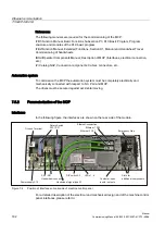
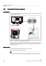
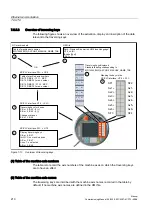
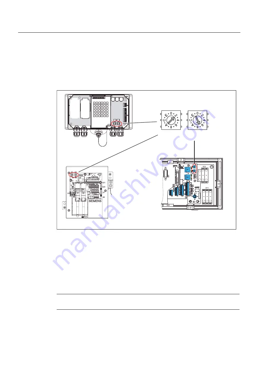
The following figure displays the relevant position of the rotary coding switches S1 and S2 in
the different power supply units.
5RWDU\FRGLQJVZLWFK
6
6
7HUPLQDOER[b31b%DVLFDQG
7HUPLQDOER[313OXV
0DFKLQH3XVKEXWWRQ37&
ZLWKRSWLRQDOKDQGKHOGFRQQHFWLRQERDUG
+*$+7
&RQQHFWLRQPRGXOH%DVLF31
([DPSOHIRU
Figure 7-8
Position of the rotary coding switches S1 and S2
The ID of the relevant power supply unit is defined via the rotary coding switches S1 and S2.
The setting of the ID is hexadecimal. S1 defines the higher value position, while S2 defines
the lower value position.
Ranges of values
The value range that can be defined via S1 and S2 is 0
H
to 255
H
.
The valid value range for the ID is 1
H
to 254
H
.
Note
The ID must be unique across all the existing power supply units in the system network.
Содержание SINUMERIK 840Di sl
Страница 118: ...Configuration 3 3 Connection overview Manual 118 Commissioning Manual 05 2008 6FC5397 4CP10 4BA0 ...
Страница 148: ...Power On and Power Up 5 7 License management Manual 148 Commissioning Manual 05 2008 6FC5397 4CP10 4BA0 ...
Страница 186: ...PLC commissioning 6 8 Load configuration in PG PLC STEP 7 Manual 186 Commissioning Manual 05 2008 6FC5397 4CP10 4BA0 ...
Страница 344: ...Drive commissioning SINAMICS 9 5 Basic principles Manual 344 Commissioning Manual 05 2008 6FC5397 4CP10 4BA0 ...
Страница 624: ...Glossary Manual 624 Commissioning Manual 05 2008 6FC5397 4CP10 4BA0 ...

