Technical Manual 1.05, C600 Professional
Technical Manual
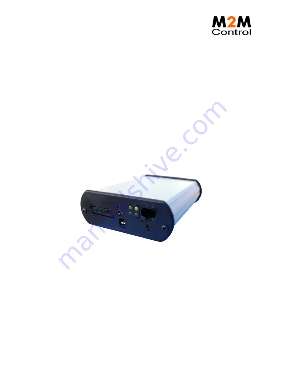
M2M Control C600 Professional
Version 1.05
Страница 1: ...Technical Manual 1 05 C600 Professional Technical Manual M2M Control C600 Professional Version 1 05...
Страница 2: ...backward compatible with previous generation of C600 units The C600 Professional includes many sophisticated features including a CAN bus interface for connection to vehicle bus networks a SD CARD re...
Страница 3: ...gital outputs 9 Digital Inputs Ignition Input 9 Analog Inputs 11 Serial port 1 programming port RS485 port 11 Serial port 2 12 CAN 13 1 Wire 14 DC Out 14 Headset connector 15 Installing the SIM card 1...
Страница 4: ...y Infranet Technologies GmbH Ph 49 40 69647 260 Tempowerkring 2 Fax 49 40 69647 259 21079 Hamburg Email info m2mcontrol de Germany Web www m2mcontrol de Technical Manual 1 05 C600 Professional Page 4...
Страница 5: ...y accessed by the user SIM Card SD CARD DIP Switch Headset LED s and RS232 The back plate holds all connectors necessary for installation 4 pin for Power and ignition 6 pin for RS232 Programming 12 pi...
Страница 6: ...bus H signal 4 Voice External voice 5 RS485A RS485 A signal 6 RS485B RS485 B signal 7 1W LED 1 Wire ID Button LED 8 SGND Signal Ground 9 CAN L CAN bus L signal 10 SGND Signal Ground 11 SGND Signal Gro...
Страница 7: ...8 RTS Request To Send Accessories available from M2M Control for cable assembly Order code Name RT O TYCO H4 TYCO p n 794617 4 TYCO Connector house 4 pins Bag with 10 pcs RT O TYCO H6 TYCO p n 794617...
Страница 8: ...ground reference for the analog inputs The C600 is protected against wrong polarity However if the C600 unit is installed with ground connected to the C600 unit chassis for example mounted with screws...
Страница 9: ...is in low power mode Please consult the M2M Control IDE online help for more information X3 16 pin I O connector overview Pin Name Description 1 DOUT 1 Digital output 1 9 DOUT 2 Digital output 2 2 DO...
Страница 10: ...w m2mcontrol de Technical Manual 1 05 C600 Professional Page 10 of 24 X3 16 pin I O connector overview Pin Name Description 3 DIN 1 Digital input 1 11 DIN 2 Digital input 2 5 DIN 3 Digital input 3 13...
Страница 11: ...the RS DET pin must be connected to GND When using the port as general purpose RS232 the RSDET pin must be left unconnected Further details on the programming cable are available in the M2M Control ID...
Страница 12: ...Ground X2 12 pin Communication connector overview Pin Name Description 5 RS485A RS485 A signal 6 RS485B RS485 B signal 11 SGND Signal Ground Signals are inversed compared to EIA standard Serial port...
Страница 13: ...ence If the C600 is connected to a non existing network a 120 ohm resistor must be connected between CAN H and CAN L at each end of the transmission line to terminate it and avoid signal reflections B...
Страница 14: ...her information X2 12 pin Communication connector overview Pin Name Description 1 1Wire 1 Wire bus for ID Button Temperature sensor 7 1W LED 1 Wire ID Button LED 2 SGND Signal Ground DC Out A 3 3V DC...
Страница 15: ...transformer must be used to convert the signal to a single ended signal when connected to external equipment that does not have a differential balanced input Otherwise the GSM noise will not be suppr...
Страница 16: ...o use a small tool or pencil as the card for protection purposes is placed underneath the front plate surface Furthermore a mechanical lock can be slide in front of the card to prevent it from being r...
Страница 17: ...ugh VPL Please consult the M2M Control IDE online help for more information Avoid removing the SD CARD during access to the card SD Card orientation Connecting GSM and GPS antennas GSM Antenna The C60...
Страница 18: ...em LED 1 2 is yellow the unit is actively communicating with for example the M2M Control IDE program or another program supporting the C600 protocol RACP System LED 1 2 pattern overview Pattern Descri...
Страница 19: ...ins a dipswitch with two switches The dipswitch is located on the front plate for easy user access see the graphical view To use the dipswitch in the M2M Control IDE declare a Boolean input variable a...
Страница 20: ...ke sure both power supply and cables can handle the high current The battery will be charged whenever a power fail has occurred to establish the capacity making the battery ready for the next power fa...
Страница 21: ...chnologies GmbH Ph 49 40 69647 260 Tempowerkring 2 Fax 49 40 69647 259 21079 Hamburg Email info m2mcontrol de Germany Web www m2mcontrol de Technical Manual 1 05 C600 Professional Page 21 of 24 Specif...
Страница 22: ...ition Autonomous Operation in Standard Sensitivity Mode Reacquisition 1 sec Hot Start 3 5 sec Warm start 33 sec Cold start 34 sec Interface protocol NMEA 0183 v3 0 with GGA VTG GLL GSA GSV and RMC Def...
Страница 23: ...vent interruption of the communication By default reading from the CAN bus is enabled and Writing to the CAN bus is disabled by a hardware jumper inside the unit Installing this jumper and thereby ena...
Страница 24: ...below 4 Gently push the electronic board back into the encapsulation again In any case DO NOT USE FORCE If difficulty is experienced it is because the light pipes on the opposite endplate has moved a...