


Page 246
STAT
IM 2000/2000S
Service Guide
96-106775 Rev 5.0
12. Printer and Data Logger
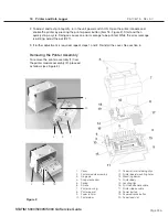
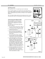
1. Remove the printer module. See ‘Removing the Printer Module’ above.
2. Unlatch the printer assembly from the printer module assembly. The printer assembly is held
into the module by two hinge pins (3). The pin on the bottom left of the assembly sits in a
recessed slot / retaining hole. The pin on the bottom right hand of the assembly is captured by a
snap mechanism. Deflect the snap (4) away from the printer to free the hinge pin, and swing the
assembly out of the module housing.
3. Remove the printer spring (5) from the left hand hinge pin and retain for re-assembly.
4. Using a #1 Phillips screwdriver, remove three screws (6) from the printer housing (7) and set
them aside for use in re-assembling the printer.
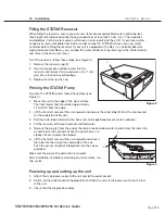
5. Remove the housing. Note the orientation of the printer board (8) and the paper roll arm (9)
assembled on the printer door (10).
6. Carefully lift the Printer Board upwards and away from the printer door. Be careful when
handling the board. The printer is integral to the wiring board. Do not place strain on the
connections of the ribbon cable soldered to the board.
7. Remove the paper roll arm from the clips (11).
8. Carefully rest the printer board beside the assembly.
Replacing the Printer
To replace the printer, proceed as follows (see Figure 2):
1. Carefully snap the paper roll arm (9), in the position shown, back into the clips (11) on the printer
door.
2. Place the printer board (8) back into position on the printer door (10). Note the alignment of the
printer board mounting holes (12) and the mounting bosses (13) on the printer door. The black
plastic printer body (14) rests between the locating ribs (15) on the inside of the printer door.
3. Check that the print head flex cable (16) and printer ribbon cable (17) are not pinched between
the printer door and the wiring board.
4. Place the printer housing (7) on the printer door (10). Check again to be sure that the flexible
cables are not pinched between the cover and the door. The power button (18) and the paper
advance button (19) must protrude through the openings in the cover and operate freely.
5. Secure the printer housing to the printer door with the three screws (6) retained during the
disassembly procedure. Do not over tighten these screws.
6. Place the printer spring (5) on the left hand hinge pin of the printer assembly, with the long arm
positioned to align with the long slot on the module housing.
7. Place the left hand hinge pin in the recesses slot / retaining hole and align the long spring arm.
Swing the right hand hinge pin towards the module housing and push firmly onto the snap
mechanism (4).
8. Replace the printer into the snap mechanism.
STAT
IM
5000/5000S/5000 G4 Service Guide


