


Page 217
STAT
IM 2000/2000S
Service Guide
96-106775 Rev 5.0
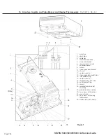
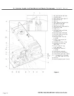
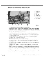
10. Armature, Isoplate, and Probe Bracket and Chamber Thermocouple
STAT
IM
5000/5000S/5000 G4 Service Guide
For Revision 7.x controller boards
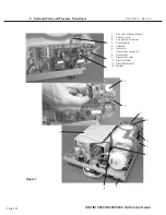
b. Connect the wires to the thermocouple connector as follows:
15. Connect the microswitch leads (4) to controller board (2) block terminal positions labelled
CASSIN.
16. Bundle the thermocouple leads, microswitch and reservoir sensor leads together using nylon
cable ties and secure the wires to the top of the armature using cable ties and the cable
anchors attached to the armature. The leads must not touch the cover when the cover is put
back on.
17. Align the probe bracket. (See section below).
18. Ensure that all fittings have been tightened and all tubes are properly secured.
19. Use a cable tie to secure the micro-switch leads and reservoir sensor leads to the side of the
probe bracket assembly AFTER the probe bracket has been aligned.
20. Check the microswitch for proper operation by inserting a cassette with the power ON and
listening for the solenoid valve to click.
21. Calibrate the unit using the appropriate calibration procedure.
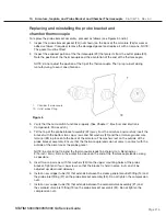
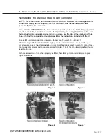
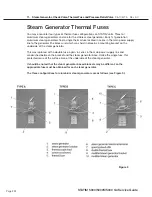
Screw 1
Screw 2
Detach wire cover
with Screws 1 & 2.
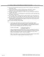
Step 1
Step 2
0.2’ (5mm)
Step 3
Shrink wrap the cut-off
ground wire to the insulation
and insert wires through
the TC connector’s rubber
O-ring.
Trim off excess ground wire.
Trim wires at 0.2 inches (5mm).
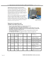
Step 4
Step 5
Reattach wire cover.
Attach Yellow wire at the “+” sign of the
TC connector and Red wire at the “-”
sign of the TC connector using Screws
3 and 4. Position the rubber o-ring into
its groove.
Screw 3
Screw 4
Rubber o-ring groove
Wire cover
Figure 7


