


Page 242
STAT
IM 2000/2000S
Service Guide
96-106775 Rev 5.0
12. Printer and Data Logger
Printer
Internal Printer
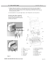
Removing and Replacing the Printer Module (where fitted).
To remove the printer module assembly (1), proceed as follows (see Figure 1):
1. Remove the cover of the STAT
im
unit. See chapter 6.
2. Place the cover (2) on a clean work surface to avoid scratching the cabinetry surface.
3. Remove the four screws (3) securing the printer module assembly to the fascia assembly (4).
Retain the screws.
4. Remove and place the printer face down on the work bench.
To replace the printer module (1), proceed as follows (see Figure 1):
1. Install the printer module assembly in the fascia assembly (4) using the four screws (3) retained
during disassembly.
2. If the module contains a new Printer Interface Board, or a new printer module, the print quality
may require adjustment. See; “Adjusting Print Quality” and “Printer Interface Board: Important
Notes.”
3. Replace the cover of the STAT
im
unit. See chapter 6.
4. Plug-in the unit power cord and turn the power switch ON.
5. Test printer.
Positioning the Ferrite Core
If the printer module assembly you are servicing was manufactured with a ferrite core attached
to the cable, the core must be present during reassembly. Position the core three to four inches
from the printer module. Apply double sided adhesive tape to the core and carefully attach it to the
fiche paper shield on the back of the printer module so the cable is not unduly strained, but will
still reach either the P2 connector on the Controller Board, or the P2 connector on the Transducer
Interface Board.
Removing and Replacing the Printer Interface Board
(module removed from fascia).
To remove the Printer Interface Board (6) from the module, proceed as follows (see Figure 1):
1. If detachable, disconnect the Printer Driver ribbon cable (9) and Printer Interface ribbon cable
(10). See Printer Interface Board: Important Notes.
2. Remove the four screws (7) from the Printer Interface Board. Retain the screws.
3. Remove and retain the Printer Interface Board and the Printer Interface Board shield (8). There
may be four nylon spacers (not shown) between the board and the stand-offs. See; “Printer
Interface Board: Important Notes.”
STAT
IM
5000/5000S/5000 G4 Service Guide


