


Page 233
STAT
IM 2000/2000S
Service Guide
96-106775 Rev 5.0
11. Steam Generator, Check Valve, Thermal Fuse and Pressure Relief Valve
STAT
IM
5000/5000S/5000 G4 Service Guide
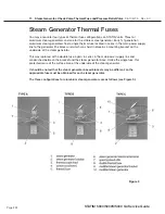
Type A is a single thermal fuse wire (5), steam generator bracket (2) and an unmodified steam
generator (1).
Type B is a double thermal fuse wire (8) with a modified steam generator bracket (9) and an
unmodified steam generator (1).
Type C is a double thermal fuse wire (8), steam generator bracket (2) with a modified steam
generator (10).
The fuse configuration for stainless steel steam generators is as follows (see Figure 10):
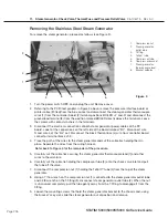
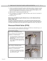
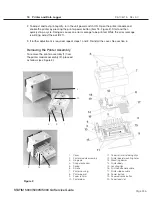
Removing the Thermal Fuse on the Aluminium Steam Generator
(for all models)
To remove the thermal fuse(s) located between the steam generator and the steam generator
bracket, proceed as follows (see Figure 11):
1. Carefully cut the high temperature rated cable tie (1) holding the compressor tube (2) onto the
check valve inlet (3) and pull the tube off the valve.
2. Disconnect the black thermal fuse lead wire (4) from controller board connector terminal J1-3
and the white wire (6) from the steam generator.
3. Trace the path of the black wire back to the base of the steam generator (5). Cut all the cable
ties holding the black wire.
4. Using a wrench, disconnect the compression nut (7) holding the Teflon™ tube (8) from the top
of the steam generator.
5. Using a wrench, disconnect the compression nut (9) holding the steam generator outlet tube
(10) to the probe bracket inlet fitting (11) and the compression (12) nut holding the steam
generator outlet tube to the steam generator outlet fitting (13).
6
7
Figure 10
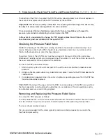
6. Upper terminal
7. Lower terminal


