


Page 157
STAT
IM 2000/2000S
Service Guide
96-106775 Rev 5.0
7. Electrical and Electronic Components
STAT
IM
5000/5000S/5000 G4 Service Guide
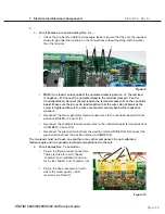
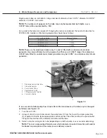
1. Turn the power switch OFF, unplug the line cord from the wall outlet and remove the
detachable line cord (1) from the unit.
2. Remove the four screws (5) holding the compressor bracket (6) to the chassis (7) and rest the
compressor to one side. Do not bend the thermocouple leads (8). See, Compressor.
3. Disconnect the leads from the A.C. inlet receptacle (3) or line filter (4) to the power switch.
Disconnect the white wire (9) from the upper spade terminal, labelled 1, and the black (10) wire
from the upper spade terminal, labelled 2, nearest the pump (11).
4. Disconnect the white wire (12) extending from Controller Board (13) terminal J1-1 to the lower
power switch spade terminal labelled 1a and the black wire (14) extending from Controller
Board terminal J1-2 to the lower power switch spade terminal, labelled 2a, nearest the pump.
5. The panel mount style switch is held into the panel with tabs. Compress the tabs (15) and
push the disconnected power switch out of the chassis wall.
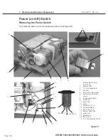
Replacing/refitting the A.C. Power Switch
To replace the power switch (2), follow these steps, (See Figure 21):
1. From a position at the rear of the unit, orient spade terminals 1a and 2a downwards and press
the power switch into the clearance hole in the chassis (7). Apply pressure evenly top and
bottom until the bezel rests against the chassis wall.
2. Connect the white wire (12) extending from Controller Board (13) terminal J1-1 to the lower
right-hand power switch spade terminal labelled 1a and the black (14) wire extending from
Controller Board terminal J1-2 to the lower left-hand power switch spade terminal, labelled 2a.
3. Connect the white wire (9) from the line filter (3) or the A.C. inlet receptacle (4) to the upper
right-hand power spade terminal labelled 1, and the black wire (10) from either the attached
power cord or the A.C. inlet receptacle to the upper left-hand spade terminal labelled 2,
nearest the pump (11).
4. Reinstall the compressor assembly (6) using the four screws (5) retained from disassembly.
Do not bend the thermocouple leads (7).
5. A dielectric strength test (Hi-Pot) AND a protective bonding impedance test (ground continuity)
must be performed on the STAT
im
when the work is completed and after the cover has been
returned to the unit.


