


Page 123
STAT
IM 2000/2000S
Service Guide
96-106775 Rev 5.0
6. Cover Assembly
STAT
IM
5000/5000S/5000 G4 Service Guide
Removing and Replacing the Membrane keypad (lCD overlay)
To remove the membrane keypad (1), proceed as follows (see Figure 3):
1. The keypad flexible cable (2) and the LCD ribbon cable (3) are secured together with double
sided adhesive tape. Carefully separate the cables.
2. Using a sturdy sharp instrument, carefully lift one corner of the membrane keypad and
CAREFULLY peel the membrane keypad away from the fascia (4). USE CAUTION, there may be
adhesive on the edges of the LCD (5). Pass the connector through the slot (6) in the fascia.
3. Remove any residual adhesive or membrane from the recessed keypad area of the fascia.
To replace the membrane keypad (1), proceed as follows (see Figure 3):
1. The replacement membrane keypad has carrier paper on the back to protect the adhesive. With
the carrier paper in place, feed the keypad cable (2) connector through the slot (6) in the fascia
(4).
2. Remove the carrier paper and align the bottom edge of the membrane keypad with the bottom
edge of the recessed area on the fascia. Carefully lower the membrane into place while
continuing to draw the keypad cable connector through the slot. With finger pressure only,
press the membrane into place, eliminating air pockets under the membrane.
3. Secure the keypad cable and LCD cable together using dual sided adhesive tape.
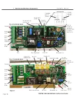
4. Connect the keypad cable connector to controller board (7) P4.
5. Connect the right angle LCD cable connector to controller board P3.
6. Connect the printer cable (8) connector, if present, to controller board P2 or pressure interface
board (9) connector P2, if present. The printer cable in Figure 3 shows a ferrite core (10). This
core may or may not be present. If present, the core must be attached to the wall of the printer
module before replacing the cover.
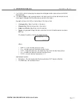
7. Plug in the power cord and power the unit ON. To test each button on the keypad ensure that
the cassette is not engaged, or that it is out of the unit. Select a cycle and press the START
button. The LCD message reads, “INSERT CASSETTE”. Repeat this step for each cycle to
ensure the keypad is functioning properly. To test the STOP button select a cycle. The LCD
message indicates which cycle is selected. Press the STOP button. The LCD message reads,
“SELECT A CYCLE”.
8. Reinstall the cover. See Cover Removal and Replacement, above.


