


Page 215
STAT
IM 2000/2000S
Service Guide
96-106775 Rev 5.0
10. Armature, Isoplate, and Probe Bracket and Chamber Thermocouple
STAT
IM
5000/5000S/5000 G4 Service Guide
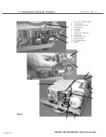
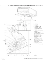
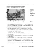
7. Chamber thermocouple
19. Outlet probe fitting
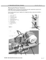
Figure 6
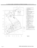
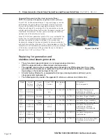
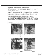
Replacing and reinstalling the probe bracket and
chamber thermocouple
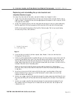
To replace the probe bracket assembly, proceed as follows (see Figures 5 and 6):
1. Inspect the probe bracket gasket (24) (not shown) on the back of the armature (26) for wear or
adhesive failure. If required, remove the damaged gasket and replace it with a new one. NOTE:
The gasket must be fitted.
2. Inspect the exposed portion of the thermocouple (29) that projects from the outlet probe (30).
Note the position of the thermocouple and the orientation of the end of the thermocouple.
NOTE: do not adjust the position of the tip of the thermocouple. The tip is pre-bent during
manufacturing to exact specifications.
3. Verify that the microswitch functions properly. (See Chapter 7. Electrical and Electronic
Components: Microswitch).
4. Tilt the top of the probe bracket assembly (22) away from the armature and carefully insert the
bracket with the bottom two cap screws and flat washers (23) and the armature ground wire
terminal (28) in place onto the back of the armature. The washers rest on the outside of the
probe bracket assembly. Ensure that the thermocouple leads do not come in contact with the
outside of the armature or the probe gasket.
NOTE: be careful not to bend the thermocouple leads too sharply (min. Bend radius -
3/16 inch / 5mm). Retain the protective sleeve on the end of the thermocouple leads as long
as possible.
5. Insert two cap screws with flat washers (23) into the upper mounting holes of the probe
bracket. Tighten all four cap screws so that the bracket is held in place, but can still be
adjusted up, down and sideways.
6. Install a new copper tube (13) that extends between the steam generator outlet fitting (14) and
the probe inlet fitting (27) on the probe bracket assembly (22). Do not tighten the compression
nuts.
7. Install a new copper tube (18) that extends between the solenoid valve assembly (21) and
the solenoid valve inlet fitting (19) on the probe bracket assembly (22). Do not tighten the
compression nuts.


