


Page 153
STAT
IM 2000/2000S
Service Guide
96-106775 Rev 5.0
7. Electrical and Electronic Components
STAT
IM
5000/5000S/5000 G4 Service Guide
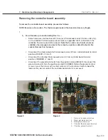
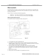
Replacing the Microswitch
To replace and refit the microswitch, proceed as follows (see Figure 19):
1. Using the two screws (3) retained from the removal procedure, attach the microswitch to the
probe bracket with the hinge end of the switch arm up and facing towards the front of the unit.
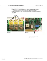
2. Connect the microswitch leads (1) to controller board (2) block terminal positions labelled
CASSIN. The red wire is inserted into CASSIN J4-1 (J3-1) for Rev 3.0 boards), the blue wire is
inserted into CASSIN J4-2 (J3-2 for Rev 3.0 boards). Secure the leads.
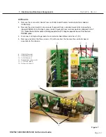
3. Route the microswitch leads back into the wiring harness and secure the complete harness
using cable ties every 2-3 inches. Secure these to the top of the armature using the clamps
provided.
4. There are two methods of testing the microswitch.
a. Plug-in the power cord and turn the power switch ON. When the unit is powered ON and
the cassette is inserted, the solenoid valve is activated. Carefully insert the cassette. If
the solenoid valve “clicks” before the cassette is fully inserted, the microswitch needs to
be adjusted. If the solenoid valve does not “click” after the cassette is fully inserted, the
microswitch needs to be adjusted or it is defective.
b. Using a multimeter set at continuity, touch the meter probes across controller board
terminal positions labelled CASSIN. If continuity is achieved before the cassette is fully
inserted, the microswitch needs to be adjusted. If continuity is not achieved after the
cassette is fully inserted the microswitch needs to be adjusted or it is defective, see
Adjusting the microswitch.
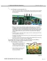
5. Once installed and functioning, apply a thin bead of RTV silicone sealant along all edges of
the microswitch that are in contact with the probe bracket. Allow the silicone to cure per
manufacturer’s instructions.
6. Run a sterilization cycle and observe the area around the microswitch for leaks.
Adjusting the Microswitch
1. If adjustment is required, power the unit OFF. Remove the screws securing the microswitch
to the probe bracket and remove the microswitch. Using fine needle-nose pliers, adjust the
activation point of the switch by carefully bending the microswitch arm. Reinstall and re-test
the switch.


