


Page 129
STAT
IM 2000/2000S
Service Guide
96-106775 Rev 5.0
6. Cover Assembly
STAT
IM
5000/5000S/5000 G4 Service Guide
Reinstalling the STAT
IM 5000 G4 Cover
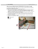
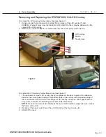
To reinstall the cover, follow these steps (see Figure 5).
1. Inspect the armature gasket located on the inside front portion of the cover. If it is damaged
or fails to adhere to the surface of the cover, it must be replaced. See,
Replacing the Armature
Gasket following.
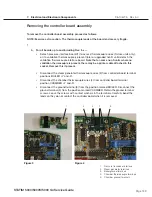
2. Remove the reservoir cap (3) from the top of the reservoir.
3. Rest the cover (1) beside the left side of the unit. Reconnect the LCD connector (9) to
controller board header P3, and the LCD’s DC power source cable (10) to the LCD controller
board (11) located in the fascia.
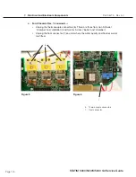
4. Reconnect the power cord (2) and power the unit ON to check that the LCD is functioning.
After checking, turn the power switch OFF and unplug the power cord.
5. Carefully lift the cover from the work surface. While rotating the cover slide it forward until the
fascia clears the controller board (8) and the front of the armature.
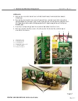
6. Tilt the front of the cover down and the rear of the cover upwards. Carefully reposition the
front portion of the cover back over the front of the controller board and armature.
Be CAReFul NoT To PINCH THe RIBBoN CABle.
7. When the front of the cover is in place, lower the rear portion of the cover, and gently push
backwards. Ensure the three tabs at the bottom of the fascia are properly lined up with the
three holes in the front of the chassis. Carefully realign the screw holes at the back and re-
insert three screws with lock washers (5) across the rear of the unit (TIP: start with the rear
center screw).
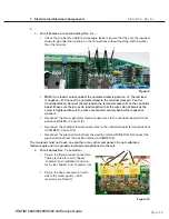
8. Re-insert the four remaining screws (4), two on each side. Press firmly on the top of the cover
to compress the gaskets and partially re-insert the screws as the holes align. When in place,
tighten all the screws. Do not over tighten the screws.
9. Place the reservoir cap (3) back onto the reservoir.
10. Reconnect the power cord.


