


Page 228
STAT
IM 2000/2000S
Service Guide
96-106775 Rev 5.0
11. Steam Generator, Check Valve, Thermal Fuse and Pressure Relief Valve
1. Make sure the power switch is OFF, and the unit is unplugged.
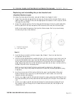
2.
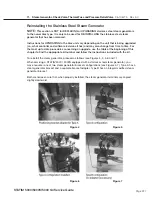
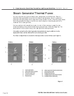
a. To refit a Type A configuration, place the bracket into position by aligning the dimple on
the bottom of the adapter with the hole in the chassis (See Figure 4). Place the stainless
steel steam generator on top of the bracket adapter (See Figure 5). Align the bracket’s key
slots with the screws on the chassis and tighten just enough to keep the assembly in place
(See Figure 6).
b. To refit a Type B configuration (See Figure 7), align the steam generator and integral
bracket key slots with the screws on the chassis. But do not tighten yet.
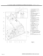
Refer back to Figure 3 for the remainder of the procedure.
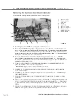
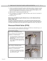
3. Reconnect the compression nut (1) on the steam generator tube to the T-fitting (3) on the
steam generator.
only finger tighten at this stage
.
4. When the nut is fully on the fitting, tighten the two screws holding the steam generator bracket
assembly to the chassis.
5. Now, using a 3/8 wrench on the T-fitting and a 7/16 wrench on the compression nut, tighten
the two together.
Do not overtighten
.
6. Reconnect the compression nut of the Teflon™ tube (4) to the top of the steam generator.
Thread the nut finger tight, then tighten.
Do not overtighten
.
7. Carefully push the compressor tube (5) onto the check valve inlet and secure the tube to the
valve using a high temperature rated cable tie.
8. Re-route the power cables in the wiring harness along the back of the chassis and connect
them to the controller board. The black wire to goes to connection marked L and the white
wire to connection marked N. Re-secure the wiring harness with cable ties.
9. Check the bend and route of the steam generator thermocouple lead (6) and place alongside
the chamber thermocouple lead to the controller board. The leads must not touch the cover
when the cover is assembled to the chassis.
10. Reconnect the ground lead terminal to the position marked BOILER directly above the
thermocouple terminals on the controller board.
11. Check the pre-bend on both thermocouple leads to ensure that they are the required shape to
go under the washers on the connections without touching anything other than the terminal.
CAuTIoN:
The thermocouple leads at the board end are very fragile.
The unmarked lead is positive, +Y, and red lead is negative, -R. Connect the unmarked lead
to the terminal Y on the controller board. Connect the red lead to the terminal
marked -R on the controller board. Make sure there is extra lead length so that the wires do
not break as the screw is tightened. ensure that the wires are seated securely behind the
respective washers (see Figure 2 detail).
The two leads must not touch one another or any other component. Do not calibrate a
thermocouple until it is properly installed and positioned in the unit.
12. Bundle the chamber thermocouple lead, the steam generator thermocouple lead, the
validation thermocouple lead (where fitted), pressure transducer leads (where fitted), micro
switch leads and reservoir sensor leads together using cable ties, approximately every 2-3
inches. Secure the wires to the top of the armature using the cable anchors provided.
13. Replace the pressure interface board or printer cable (if fitted) into the blue socket.
STAT
IM
5000/5000S/5000 G4 Service Guide


