


Page 211
STAT
IM 2000/2000S
Service Guide
96-106775 Rev 5.0
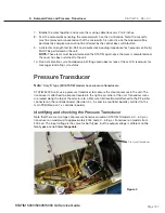
10. Armature, Isoplate, and Probe Bracket and Chamber Thermocouple
STAT
IM
5000/5000S/5000 G4 Service Guide
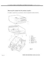
cassette in the unit during operation.
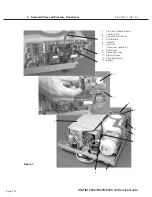
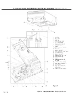
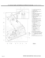
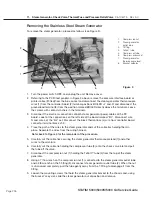
To remove the isoplate assembly (1) from inside the armature (2) proceed as follows (see Figure 2):
1. If not already undertaken, remove the armature from the chassis and place it on a secure work
surface (see above).
2. Remove the three screws (3) securing the bubble level (4) to the bubble level base (5) on
the front right corner of the armature. (The bubble level obscures a fastener that must be
removed.)
3. The drain tube (6) passes through the bottom of the armature near the probe bracket opening
and is attached to the isoplate. Using a pair of pliers, pull the drain tube off and retain.
4. The isoplate is secured in the armature using screws with washers (7) on the top and bottom
of the armature. Remove and retain all the screws with washers.
5. When all fasteners are removed, slide the isoplate out of the armature.
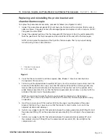
Replacing and reassembling the isoplate into the armature
To install the replacement isoplate, proceed as follows (see Figure 2):
1. Slide the isoplate (1) into the armature. This may be easier if the cassette is first inserted into
the isoplate. Note the orientation of the probe bracket opening in the back wall of the isoplate.
Reinstall the screws with washers (7) but do not tighten the screws. When all the screws are
reinstalled, slide the cassette into the isoplate if it is not already installed. Now tighten the
screws in an “X” pattern, alternating across the isoplate, from the outside to the center.
2. Install the drain tube (6) and secure using Locktite™ LM113.
3. Reinstall the armature into the chassis (see Armature above).
4. Reinstall the bubble level (4) to the bubble level (5) base using the three screws (3) retained
from disassembly.
5. Before reinstalling the probe bracket assembly to the back of the armature, ensure that all
traces of the old probe bracket gasket (8) are removed from the bracket. Fit a new gasket as
appropriate. Note that a new gasket comes attached to the replacement isoplate and with a
replacement probe bracket. It is also available separately.
6. Refit and re-align the probe bracket and chamber thermocouple assembly (see
Aligning the
probe bracket and chamber thermocouple assembly below
).
7. A dielectric strength test (Hi-Pot) and a protective bonding impedance test (ground continuity)
should be performed on the STAT
IM unit at this stage.
NOTE:
These tests must be performed on the STAT
im
again once the work is completed and
the cover has been returned to the unit.
8. Refill the reservoir using steam process distilled water.
9. Recalibrate the thermocouples.
10. Run a sterilization cycle and observe all fittings and tubes for leaks. Check LCD read-outs for
messages indicating cycle status.


