


Page 176
STAT
IM 2000/2000S
Service Guide
96-106775 Rev 5.0
8. Water Pumps, Reservoir, and Compressor
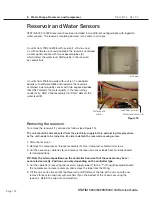
Reservoir and Water Sensors
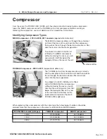
STAT
IM 5000 / 5000S reservoirs have been installed in two different configurations with regard to
water sensors. The reservoir moulding however is the same in all cases.
On units from 1995 to 2008 with revision 2.x/5.x/6.x and
7.x with software up to revision R604, the reservoir contained
a water quality sensor with two exposed probes (2),
which detect the water level AND quality in the reservoir
by conductivity.
On units from 2008 onwards with revision 7.x controller
boards with software R605 and upwards, the reservoir
contained a water quality sensor with two exposed probes
that ONLY detects the water quality in the reservoir by
conductivity, AND a float assembly that ONLY detects the
water level (3).
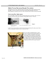
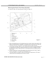
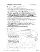
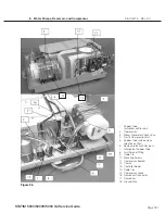
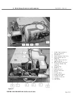
Removing the reservoir
To remove the reservoir (1), proceed as follows (see Figure 19):
The unit should be disconnected from the electricity supply before performing this procedure
as the unit needs to be turned on it’s side to detach the reservoir securing screw.
1. Drain the reservoir.
2. Remove the compressor / bracket assembly (3). See, Compressor. Retain all screws.
3. Cut the necessary cable ties (6) and remove the reservoir sensor leads from controller board
terminal positions.
TIP: Note the terminal positions on the controller board so that the sensors may be re-
connected correctly. Positions can vary depending on the controller type.
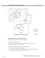
4. Cut the cable tie (4) securing the reservoir supply tube (7) to the “T”-fitting (8) located beneath
the compressor / bracket assembly and remove the tube from the fitting.
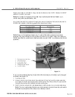
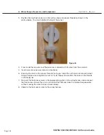
5. Tilt the unit on its side so that the Reservoir and PCB are at the top of the unit. Locate and
remove three nylon cap nuts with washers (9) on the bottom of the chassis securing the
reservoir. Retain the cap nuts and washers.
STAT
IM
5000/5000S/5000 G4 Service Guide
Figure 18
Water quality
sensor
Water level sensor (3)
(cut-away)
(seen from exterior)


