


Page 142
STAT
IM 2000/2000S
Service Guide
96-106775 Rev 5.0
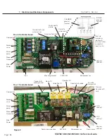
7. Electrical and Electronic Components
Replacing/Refitting the Controller Board Assembly
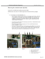
To replace/refit the controller board assembly, proceed as follows:
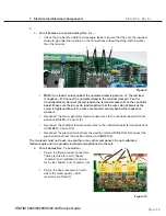
1. Visually inspect the controller board assembly to ensure that there is sufficient thermal
compound on the mounting bracket directly below the steam generator triac.
2. Install the controller board assembly using the three screws (13) with washers retained from
removal (or fit new if replacing with a new board).
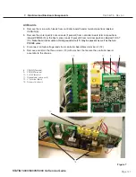
3. Connect the high voltage leads from the power switch, steam generator, pump, solenoid
valve and compressor to controller board J1 terminal (12). Each lead is numbered with a
corresponding J1 designation. See Table B.
TABle B: CoNTRolleR BoARD HIGH volTAGe J1 CoNNeCToR
Marking
Fuse value
Device
Signal
Wire Colour
COMP
J1-10
J1-9
COMPRESSOR
N
L
WHITE
BLACK
VALVE
J1-8
J1-7
SOLENOID
VALVE
N
L
WHITE or RED
WHITE or RED
PUMP
J1-6
J1-5
PUMP
N
L
WHITE
BLACK
BLR
J1-4
J1-3
STEAM
GENERATOR
N
L
WHITE
BLACK
INPUT
J1-2
J1-1
POWER
SWITCH
L
N
BLACK
WHITE
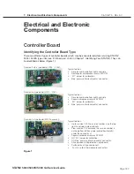
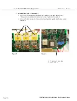
4. Connect the microswitch leads to controller board header positions labeled CASSIN (8).
5. Connect the water quality sensor leads (if present) to controller board positions labeled
PROBE (9) or the float sensor leads (if present) to terminal positions labeled FLOAT (10).
Note that on later units a third, ground wire may be present as well as the two PROBE wires.
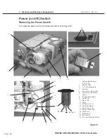
Figure 7
Figure 8
8
9
10
12
STAT
IM
5000/5000S/5000 G4 Service Guide


