


Page 241
STAT
IM 2000/2000S
Service Guide
96-106775 Rev 5.0
12. Printer and Data Logger
STAT
IM
5000/5000S/5000 G4 Service Guide
Printer and Data Logger
STAT
im
5000/5000S units are capable of operating several printing or data recording devices
depending on the model.
The following is an overview of unit variants and what can and cannot be used with them:
1995 – 2007: STAT
im
5000/5000S units with revision 2.x/5.x or 6.x controller board
• These were available both with and without a built-in STATPRINTER mechanism located
on the left side of the front fascia.
• The internal printer mechanism is the same as the STATPRINTER mechanism usually
associated with the external 2000/2000S STATPRINTER unit.
• Units purchased WITHOUT a printer can be retro-fitted with a printer module using part
number 01-210000 “Thermal Internal Printer Kit for STAT
im
5000/5000S”.
• Note that a SciCan Data Logger cannot be fitted to these units as the chassis
cannot accommodate the installation of the appropriate cable port.
2007 onwards: STAT
im
5000/5000S units with revision 7.x controller board
• These units are also available both with and without a built in STATPRINTER mechanism
located on the left side of the front fascia.
• Units purchased WITHOUT a printer will have a 9-pin RS232 port located on the rear of
the chassis for connecting an external (generic) printer OR a SciCan Data Logger.
• These units can also be retro-fitted with a printer module using part number 01-210000
Thermal Internal Printer Kit for STAT
im
5000/5000S.
• Units WITH an internal printer DO NOT have a 9-pin RS232 port on the rear of the
chassis but DO have a cutout in the chassis to retro-fit a port using part number 01-
110222S “RS232 Port Kit, STAT
im
5000/5000S” should you wish to convert a printer
unit to a Data Logger unit.
General notes:
For revision 2.x/5.x/6.x controller boards
• The printer cable connector on 5000 non S units is attached to the
P2 connector on the
main PCB.
• The printer cable connector on 5000 S units is attached to the
P2 connector on the
pressure interface PCB.
For revision 7.x controller boards
• The printer cable connector or RS232 internal port connector on ALL 5000/5000S units
is attached to the
SERIAL connector on the main PCB.
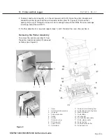
For all units
• Some internal printer module assemblies were manufactured with a ferrite core
assembled to the cable. If so, ensure the ferrite core is in place when the assembly is
reinstalled. See; “Positioning the Ferrite Core”.


