


Page 199
STAT
IM 2000/2000S
Service Guide
96-106775 Rev 5.0
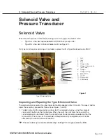
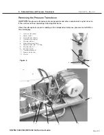
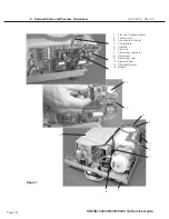
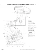
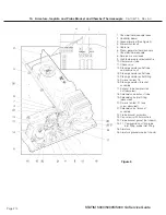
9. Solenoid Valve and Pressure Transducer
STAT
IM
5000/5000S/5000 G4 Service Guide
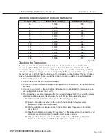
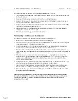
Checking output voltage on pressure transducer
Pressure [kPa]
68PSI sensor reading [v]
60PSI sensor reading [v]
93
1.2934
1.3992
94
1.3020
1.4089
95
1.3105
1.4186
96
1.3190
1.4282
97
1.3276
1.4379
98
1.3361
1.4476
99
1.3446
1.4573
100
1.3532
1.4669
101
1.3617
1.4766
102
1.3702
1.4863
103
1.3788
1.4959
104
1.3873
1.5056
105
1.3958
1.5153
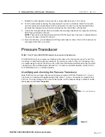
Checking the Transducer
The pressure transducers used on STAT
im
units are electro-mechanical in operation. When
pressure is applied to the mechanical components located in the base of the transducer, the
movements of the components are translated into a voltage signal in the electronics by modifying
a fixed input voltage signal to give a value corresponding to the pressure applied. If you suspect
that the transducer is faulty then the function of the transducer can be checked. The unit will need
to be set up correctly before checking, and the following must be undertaken prior to diagnosis.
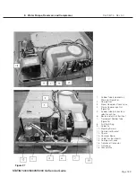
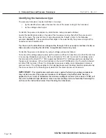
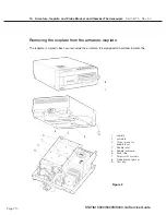
1. Remove the cover of the unit.
2. Attach the control box to the PCB (all models).
3. Power up the unit in calibration mode as appropriate to the software revision (see calibration
section).
4. Connect a multimeter to the control box Vref output and check/adjust the reference voltage
as appropriate (n/a on revision 7 units).
5. The atmospheric pressure transducer offset value needs to be set at ‘00’ to correct the display
pressure reading to perform the following checks. If it is not, then proceed as follows:
5.1. Write down the transducer atmospheric offset reading (e.g. FE).
5.2. Insert a calibration cassette into the unit with the calibrated reference meters
(temperature and pressure) attached.
5.3. Start a calibration cycle appropriate to the unit and adjust the pressure transducer
offset to ‘00’
5.4. Stop the calibration and release the cassette from the probe bracket to enable the unit
and pressure reference meter to read the atmospheric pressure.
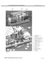
5.5. Using a 3/8-inch wrench, disconnect the compression nut (8) holding the coiled
transducer tube (6), from the bottom of the transducer (see Figure 4).
Figure 5


