


Page 195
STAT
IM 2000/2000S
Service Guide
96-106775 Rev 5.0
9. Solenoid Valve and Pressure Transducer
STAT
IM
5000/5000S/5000 G4 Service Guide
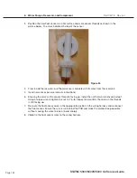
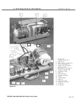
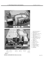
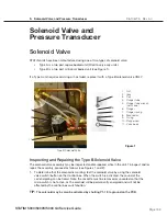
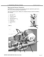
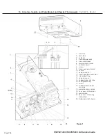
7. Remove the plunger (6), plunger spring (7) and bronze disc (8) from the valve plunger tube
body.
8. Inspect the o-ring (9) and the plunger seal (10) for nicks, compression set or swelling (the seal
should not extend more than 0.010 inches from the plunger body).
9. Inspect the valve body (11) for debris. If the debris appears to be fragments of rubber, inspect
the cassette seal for damage.
10. Clean the valve plunger, valve body, and fittings using oil free compressed air to blow debris
from the surfaces. If there is residue (e.g. congealed handpiece oil), on the surfaces of the
inside of the tube and outside of the plunger they may be cleaned with a moistened cleaning
pad designed for use with Teflon™ coated surfaces to remove it. DO NOT USE METALLIC
OBJECTS TO REMOVE THE RESIDUE. After cleaning, rinse thoroughly with water to remove
all traces of the detergent.
11. Once the valve components have been inspected, determine if the assembly needs cleaning
only, a new coil, the repair kit for the solenoid valve or an entire valve assembly replacement.
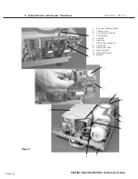
12. Reinstall or replace; the bronze disc (8), plunger spring (7), plunger (6) and o-ring (9) to the
plunger tube (4). (Order SciCan Kit Part # 01-100998S.)
13. Screw the plunger tube into the valve body (11) and tighten using the solenoid tube wrench.
14. Place the coil (3) inside the yoke (2) and place onto the plunger tube.
15. Reinstall the coil retaining nut (1).
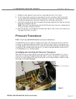
16. Connect the leads to controller board terminal block positions labeled J1-7 LINE and J1-8
NEUTRAL. These two wires are interchangeable.
17. Test the solenoid by activating the solenoid switch on the control box
Note:
the cassette must be remove or unseated so that the microswitch is not active as
the solenoid will be permanently energized and will not be affected by the control box
switch/button.
18. If the solenoid valve assembly or the solenoid coil is replaced, a dielectric strength test (Hi-Pot)
and a protective bonding impedance test (ground continuity) MUST be performed on the unit.
NOTE:
These tests must be performed on the STAT
im
again once the work is completed and
the cover has been returned to the unit.
19. Replace any cable ties cut during the procedure.


