


Page 151
STAT
IM 2000/2000S
Service Guide
96-106775 Rev 5.0
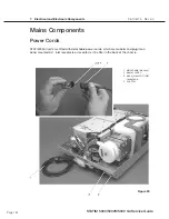
7. Electrical and Electronic Components
STAT
IM
5000/5000S/5000 G4 Service Guide
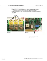
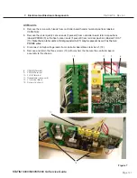
c.
For revision 6.x and 7.x controller boards AND units with adaptor boards installed as
part of an Alex steam generator upgrade —
Remove the microprocessor from Controller
Board Socket using a 44-pin PLCC IC puller. Remove the EEPROM device from Controller
Board socket using an 8-pin IC puller.
DISCARD the microprocessor and EEPROM devices.
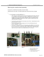
Replacing/refitting the Microprocessor (and Pre-Programmed
eePRoM where fitted).
The microprocessor and EEPROM devices are a matched pair set. These devices must be ordered and
installed together. An attempt to substitute either device singly results in a continuous beeping tone.
Note:
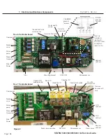
The orientation of the various main microprocessor types (see Figures 17 and 18 above)
to ensure correct alignment. ensure that the device pins are fully inserted into the socket.
Incorrectly installed IC devices may cause damage to the unit.
ALL EEPROM devices are notched in a similar manner to the 40-pin microprocessor.
To replace/retrofit the microprocessor, proceed as follows:
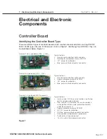
1. Determine the part number and revision of the installed controller board. (This number appears
on the component side of the board in the lower right-hand corner.) Determine the rated voltage
of the unit by examining the serial number label. Use this information to find the appropriate
microprocessor replacement kit.
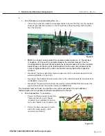
2.
a.
For revision 2.x/5.x, 3.x/4.x controller boards, use an insertion tool to install the
microprocessor into controller board socket. Note the orientation of pin #1 of the
socket and microprocessor.
b.
For revision 6.x and 7.x controller boards AND units with adaptor boards installed as
part of an Alex steam generator upgrade, the microprocessor can be inserted into
controller board socket by hand. Note the orientation of pin # 1 of the microprocessor
and align it with the notch in the PlCC socket.
3.
For all controller boards where an eePRoM is fitted, using an insertion tool, insert the
eePRoM device into controller board socket. Note the orientation of pin #1 of the socket
and eePRoM.
4. Connect the keypad connector to controller board.
5. Connect the LCD connector to controller board.
6. Connect the printer connector to controller board, if present.
7. Power the unit ON. Ensure that the version number displayed briefly when the unit is first
powered (not Rev. 3.x/4.x) matches the version number printed on the microprocessor. If the
LCD fails to display the “select a cycle” message, review the wiring connector placement and
check that the microprocessor and EEPROM are positioned properly in the sockets.
8. Calibrate the unit after the installation of a new microprocessor.


