


Page 219
STAT
IM 2000/2000S
Service Guide
96-106775 Rev 5.0
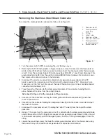
10. Armature, Isoplate, and Probe Bracket and Chamber Thermocouple
STAT
IM
5000/5000S/5000 G4 Service Guide
b.
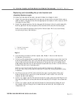
If the probe alignment jig is NoT being used:
1. Insert a regular cassette (the cassette normally used by the customer with the unit is
preferred) or a calibration cassette into the armature until it just touches the probe tips.
2. Gently push the cassette towards the probe bracket, while at the same time adjusting
the probe bracket until the probe tips enter the openings in the cassette lid. PERFORM
THIS OPERATION WITH CARE. DO NOT BEND THE TIP OF THE CHAMBER
THERMOCOUPLE.
3. Slowly push the cassette to the fully inserted position while continuing to adjust the
probe bracket so as to centre the probes in the cassette openings.
4. Withdraw the cassette and repeat steps 2 and 3 as often as required to centre the
probes correctly in the openings.
5. Using the Allen key, tighten the four cap screws with flat washers in the following
tightening pattern: upper left hand corner, bottom right hand corner, upper right hand
corner and the bottom left hand corner.
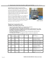
3. Ensure that all fittings have been tightened and all tubes are properly secured.
4. Plug in the power cord and turn the power switch ON. Start an UNWRAPPED cycle and watch
the LCD until the PRESSURIZING or CONDITIONING phase of the cycle is displayed.
5. At this point, turn the power switch OFF. This will close the solenoid valve and should retain
pressure in the machine.
Caution:
the steam generator, check valve, probe bracket and associated tubing will be
hot. There is steam pressure in the unit so care should be taken when observing the unit.
Guard against burns.
6. Observe the unit and check for visible or audible signs of steam leakage. Note any leaking
joints.
7. Turn the unit back on, and allow it to vent.
Caution:
allow the unit to cool sufficiently before attempting adjustments
.
8. Tighten any leaking joints or fine tune the probe bracket alignment as above if appropriate.
Repeat steps 4 to 6 as necessary until no leaks are observed.
9. Make sure that all brackets are secured to the chassis and cable ties are installed.
10. Calibrate the unit using the appropriate calibration procedure.
11. Run a sterilization cycle and observe all fittings and tubes for leaks. Check LCD read-outs for
messages indicating cycle status.


