


Page 203
STAT
IM 2000/2000S
Service Guide
96-106775 Rev 5.0
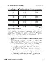
9. Solenoid Valve and Pressure Transducer
STAT
IM
5000/5000S/5000 G4 Service Guide
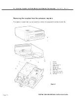
Removing the Pressure Interface Board
NoTe:
This is only applicable to Revision 2.x, 5.x and 6.x controller boards. All controller
boards from Revision 7 have the pressure circuitry integrated into the main board.
CAuTIoN:
Hazardous voltages are accessible on the controller board when the power is on.
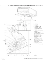
The pressure interface board is a piggyback board assembly, which is attached to the P2 printer
connector of the controller board (see note above) using the latch mechanism of the P2 header.
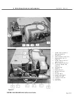
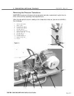
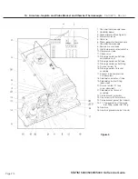
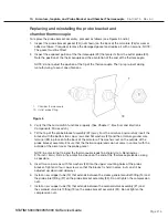
To remove the Pressure Interface Board (1), proceed as follows (see Figure 7):
1. Turn the power switch (2)
oFF
, and unplug the power cord (3) (not shown).
2. Disconnect the printer cable (4) (if present) from pressure interface board connector P2.
3. Disconnect the transducer wires (9) from pressure interface board terminal positions P1-1
‘SIG’ (blue wire, signal), P1-2 ‘V+’ (red wire V+) and P1-3 ‘GND’ (black wire, ground).
4. Press the ejector latches (10) of controller board (11) connector P2 to unseat the pressure
interface board and remove the board.
Reinstalling the Pressure Interface Board
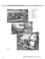
To reinstall the pressure interface board (1), proceed as follows (see Figure 7):
1. Orientate the pressure interface board with the component side of the board facing away from
the controller board (11) and the P2 connector on the left-hand side. Gently seat the pressure
interface board onto the controller board P2 connector until the ejector latches are in an
upright position. Do not crush or pinch the thermocouple leads. Support the controller board
to avoid excessive deflection when pressing the interface board onto the connector.
2. Connect the transducer wires (9) to Pressure Interface Board terminal positions P1-1 ‘SIG’
(blue wire, signal), P1-2 ‘V+’ (red wire V+) and P1- 3 ‘GND’ (black wire, ground).
3. Connect the printer cable (4) (if present) to the pressure interface board connector P2. Ensure
that Pin 1 of the keyboard cable aligns with Pin 1 of pressure interface board P2.
4. Plug in the power cord (3) (not shown) and turn the power switch (2)
oN
.
5. Run a sterilization cycle and observe LCD read-out for messages indicating cycle status.
Important:
the pressure transducer performs a critical process monitoring function during the
sterilization cycle, and on later units the calibration data is stored on the interface board. The
unit must be re-calibrated prior to the being used to process instruments. Refer to the relevant
calibration procedure and re-calibrate the unit upon completion of the repair.


