


Page 224
STAT
IM 2000/2000S
Service Guide
96-106775 Rev 5.0
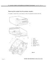
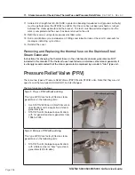
11. Steam Generator, Check Valve, Thermal Fuse and Pressure Relief Valve
1. Turn the power switch
oFF
, and unplug the unit. Remove cover.
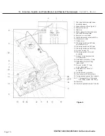
2. a.
For all controller boards other than revision 7.x —
Remove the pressure interface
board or printer cable (if fitted) from the blue socket and disconnect the steam generator
thermocouple wires (1) from Controller Board (2) terminal positions Y and -R and
disconnect the ground lead terminal (3) from the position marked BOILER directly above the
terminals. Leave the screws with contact washers in the terminals.
b.
For revision 7.x controller boards —
disconnect the chamber thermocouple plug from the
socket on the controller board.
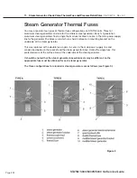
3. Disconnect the black thermal fuse (4) wire from controller board connector terminal block J1-
3.
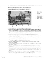
4. Trace the path of the black wire back to the base of the steam generator (5). Carefully cut all
cable ties holding the black wire.
5. Carefully cut the cable ties (6) securing the steam generator thermocouple lead (8) and other
wires to the armature (11).
6. Disconnect the white wire (12) attached to the terminal on the lower half of the steam
generator.
7. Carefully cut the cable tie (13) holding the compressor tube (14) onto the check valve inlet (15)
and pull the tube off the valve.
8. Disconnect the compression nut (16) holding the Teflon™ tube (17) from the top of the steam
generator.
9. Disconnect the compression nut (18) holding the steam generator outlet tube (19) to the steam
generator outlet fitting (20).
10. Disconnect the compression nut (21) holding the steam generator outlet tube to the probe
bracket inlet fitting (22).
11. Remove the two screws (23) holding the steam generator bracket assembly (24) to the chassis
and remove the steam generator.
Reinstalling the Aluminium Steam Generator
(for both 1st generation and Alex versions)
NoTe:
Do NoT use this section when RePlACING or uPGRADING older 1st generation
aluminium steam generators to the newer Alex type. These instructions apply only to Re-
INSTAllING an aluminium steam generator (including Alex) that has been removed.
Instructions for uPGRADING to the Alex steam generator vary depending on the status of the
unit that is being upgraded (i.e., what controller and software revisions it has) and may also
change from time to time. For the most up to date procedures concerning an upgrade, use
the table at the beginning of this chapter to find the appropriate kit number and follow the
instructions included with the kit.
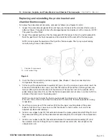
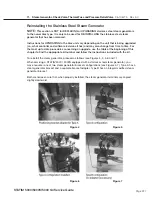
To reinstall the steam generator, proceed as follows (see Figure 2):
1. Make sure the power switch is
oFF
, and the unit is unplugged.
2. Place the steam generator in to position.
3. Connect the compression nut (18) holding the steam generator outlet tube (19) to the top
of the steam generator outlet fitting (20) and the compression nut (21) holding the steam
generator outlet tube to the probe bracket inlet fitting (22). Thread the nuts and finger tighten,
then tighten with a wrench.
Do not over tighten
.
4. Tighten the two screws holding the steam generator bracket assembly to the chassis.
STAT
IM
5000/5000S/5000 G4 Service Guide


