Page 119
STAT
IM 2000/2000S
Service Guide
96-106775 Rev 5.0
6. Cover Assembly
STAT
IM
5000/5000S/5000 G4 Service Guide
Cover Assembly
For STATIM 5000 Classic
Removing the Cover
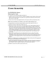
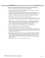
To remove the cover, proceed as follows (see Figure 1):
1. Inspect the cover (1) to ensure that it has not been damaged in transit. Position the unit on the
bench so the front leveller feet are securely on the work surface and the front cover extends
past the work surface edge.
2. Check that the LCD (2) and keypad (3) function. This requires that the unit be powered ON.
Note:
Check for symptoms of the failure to ensure that no further damage occurs.
3. Unplug the power cord (4) from the wall outlet and remove the cassette from the unit.
4. Remove the reservoir cap (5) from the top of the unit.
5. Remove seven screws from the cover; first remove two on each side (6) and then three with
lockwashers (7) at the rear of the unit, using a #2 Phillips screwdriver. Some STAT
im
5000
units are manufactured with a bacteria-retentive air filter (9) attached to the rear of the unit by
a single screw. This filter must be disconnected and the bracket (10) removed before the cover
can be removed. If the bacteria-retentive air filter is present proceed as in section 2. Filters
on the STAT
im
5000/5000S and remove the single screw securing the bracket first. Remove
the screws on either side and remove the bracket. Retain the filter, screw and bracket for
re-assembly.
6. Slowly, lift the rear portion of the cover upwards. When the cover is clear of the internal
components, carefully slide the entire cover forward to clear the front of the armature and
unsupported controller board (8). Slowly pivot the cover the same way a book opens and place
it next to the unit. The keypad and LCD are still accessible and the internal components are
exposed.
Note:
The controller board is unsupported at the front of the unit. Be careful. The keypad and
lCD cables are still attached to the controller board.
7. Observe the orientation of the ribbon cable connections: disconnect the printer connector from
controller board header P2 (if optional printer is present), the LCD connector from controller
board header P3, and the keypad connector from controller board header P4.
8. Replace the reservoir cap onto the top of the reservoir.


