6 - 10
6 DRIVE MODULE
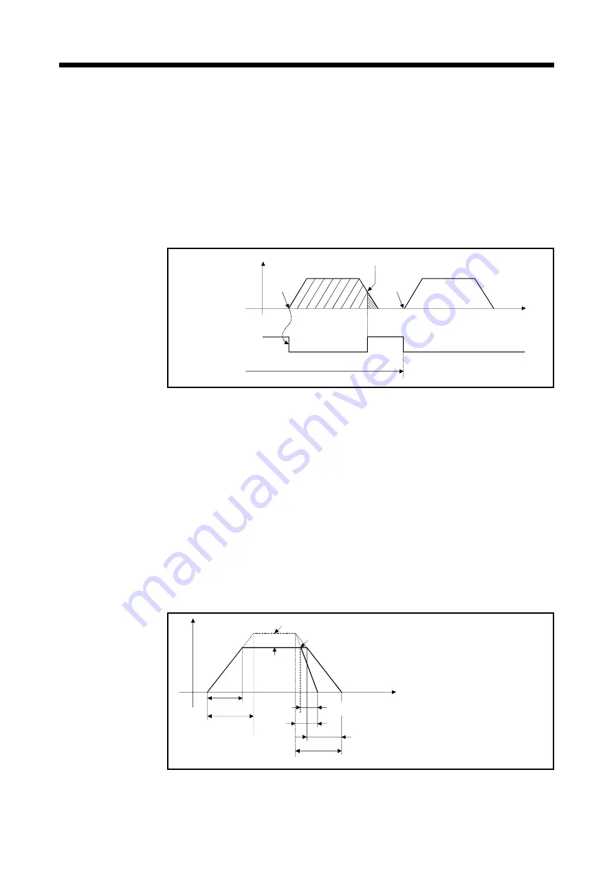
(3) Command in-position range
The command in-position is the difference between the positioning address
(command position) and feed current value.
Once the value for the command in-position has been set, the command in-
position signal (M2403 + 20n) turns on when the difference between the
command position and the feed current value enters the set range [(command
position - feed current value)
(command in-position range)].
The command in-position check is executed, continuously during position control.
(The command in-position range is not checked during the speed control and
JOG operation.)
Command in-position
(M4003+20n)
Position
control
start
Command in-position
setting value
Speed
control
start
ON
OFF
Execution of command in-position check
V
t
Fig. 6.1 Command in-position range
(4) Setting of the JOG speed restriction and parameter block No.
The JOG speed restriction and parameter block No. used in the JOG operation
are shown below.
(a) JOG speed restriction
This is the maximum speed setting at the JOG operation for virtual axis.
If the JOG speed exceeds the JOG speed restriction, the JOG speed is
controlled with the JOG speed restriction.
(b) Parameter block No. setting
This is the parameter block No. setting at the JOG operation.
The following parameter block data items are valid in the JOG operation.
• Acceleration time
• Deceleration time
• Rapid stop deceleration time
Speed
Speed limit value
Rapid stop cause occurrence
Positioning
speed set in
the servo
program
1) Real accele-
ration time
Set acceleration
time
Set rapid stop
deceleration
time
3) Real deceleration time
Set deceleration time
Time
1) Real acceleration time
Time take to reach the positioning speed
set in the servo program.
2) Real rapid stop deceleration time
Time taken to effect a rapid stop from the
positioning speed set in the servo program.
3) Real deceleration time
Time taken to stop from the positioning
speed set in the servo program.
2) Real rapid stop
deceleration time
Fig. 6.2 Relationships between the JOG speed restriction, acceleration
time, deceleration time and rapid stop time
Содержание Q Series
Страница 1: ......
Страница 19: ...A 18 MEMO ...
Страница 129: ...4 90 4 POSITIONING DEDICATED SIGNALS MEMO ...
Страница 134: ...5 5 5 MECHANICAL SYSTEM PROGRAM MEMO ...
Страница 139: ...5 10 5 MECHANICAL SYSTEM PROGRAM MEMO ...
Страница 163: ...6 24 6 DRIVE MODULE MEMO ...
Страница 201: ...7 38 7 TRANSMISSION MODULE MEMO ...
Страница 257: ...9 12 9 REAL MODE VIRTUAL MODE SWITCHING AND STOP RE START MEMO ...
Страница 267: ...10 10 10 AUXILIARY AND APPLIED FUNCTIONS MEMO ...
Страница 352: ......


