9 - 11
9 REAL MODE/VIRTUAL MODE SWITCHING AND STOP/RE-START
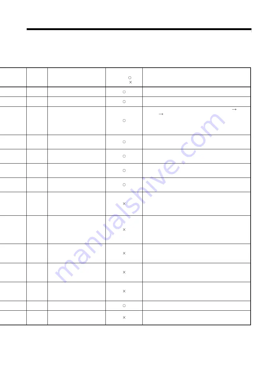
Error set
Output module operation
Operation continuation
enabled (
)/
disabled (
)
Re-start operation after stop
—
• Deceleration stop based on the
smoothing time constant.
• Continuous operation is possible by turning the stop command off (not
necessary when on) and starting.
—
• Deceleration stop based on the
smoothing time constant.
• Continuous operation is possible by turning the stop command off (not
necessary when on) and starting.
—
• Servo OFF state after deceleration
stop based on the smoothing time
constant.
• Continuous operation is possible by turning the all clutch off
all axes
servo on
clutch on.
(However, when the servomotor does not operate during the servo OFF.
Also, the clutch OFF/ON is switched as required by the user side.)
• For synchronous encoder axes, switch to the real mode, then back to the
virtual mode to resume inputs.
(Note-1)
Minor error
(200) set
(virtual axis)
• Deceleration stop based on the
smoothing time constant.
• Operation is possible by executing the real mode to virtual mode
switching request (M2043 ON), after turning the PLC ready flag (M2000)
on.
Minor error
(200) set
(virtual axis)
• Deceleration stop based on the
smoothing time constant.
• Operation is possible by executing the real mode to virtual mode
switching request (M2043 ON), after starting the Motion CPU.
—
• Deceleration stop based on the
smoothing time constant.
• Continuous operation is possible by starting after stop.
• For synchronous encoder axes, switch to the real mode, then back to the
virtual mode to resume inputs.
(Note-1)
—
• Deceleration stop based on the
smoothing time constant.
• Continuous operation is possible by starting after stop.
—
• Servo OFF state after immediate stop.
• Continuous operation is not possible due to a synchronization
discrepancy between the virtual axis and output module, and stop.
• After release the forced stop, re-align the output module in the real
mode, switch the synchronization discrepancy warning (M2046) OFF,
then switch back to the virtual mode to resume operation.
Applicable
output
module
(Servo error,
Servo error
code set)
• Servo OFF state after immediate stop
for error axis only.
• Operation is different according to the
setting at error occurrence.
• After executing a servo error reset in the real mode, re-align the axes,
switch the synchronization discrepancy warning (M2046) OFF, then
switch back to the virtual mode to resume operation.
SM512
(Motion CPU
WDT error
flag) ON
• Servo OFF state after immediate stop.
• Continuous operation is not possible due to a synchronization
discrepancy between the virtual axis and output module, and stop.
• After resetting the Multiple CPU system, re-align the output module, then
switch to the virtual mode to resume operation.
—
• Servo OFF state after immediate stop.
• Continuous operation is not possible due to a synchronization
discrepancy between the virtual axis and output module, and stop.
• After resetting the Multiple CPU system, re-align the output module, then
switch to the virtual mode to resume operation.
—
• Servo OFF state after immediate stop.
• Continuous operation is not possible due to a synchronization
discrepancy between the virtual axis and output module, and stop.
• After resetting the Multiple CPU system, re-align the output module, then
switch to the virtual mode to resume operation.
Applicable
error set
• Deceleration stop based on the
smoothing time constant.
• Operation is possible by release the error cause.
Applicable
error set
• Deceleration stop based on the
smoothing time constant.
• Return to the real mode, re-align the axes, then switch to the virtual mode
to resume operation.
(Note-1): It is input continuously for the version (Refer to Section 1.4) that supports "synchronous encoder current value monitor in real mode".
Содержание Q Series
Страница 1: ......
Страница 19: ...A 18 MEMO ...
Страница 129: ...4 90 4 POSITIONING DEDICATED SIGNALS MEMO ...
Страница 134: ...5 5 5 MECHANICAL SYSTEM PROGRAM MEMO ...
Страница 139: ...5 10 5 MECHANICAL SYSTEM PROGRAM MEMO ...
Страница 163: ...6 24 6 DRIVE MODULE MEMO ...
Страница 201: ...7 38 7 TRANSMISSION MODULE MEMO ...
Страница 257: ...9 12 9 REAL MODE VIRTUAL MODE SWITCHING AND STOP RE START MEMO ...
Страница 267: ...10 10 10 AUXILIARY AND APPLIED FUNCTIONS MEMO ...
Страница 352: ......


