User Manual
EM303B General Purpose Inverter
156
F1-04 ~Fd-08
parameters are enabled when F0-15=35. User defined V/F curve is determined
by the curve set by percentage of input frequency and percentage of output voltage. It is
linearized at different segments in different input ranges. F1-04 base frequency is the final
reached frequency of V/F curve. It is also the corresponding value to maximum output
voltage.
Input frequency percentage: Frequency base F
base
=100.0%. Output voltage percentage: Rated
voltage U
e
=100.0%. Usually frequency base is the same as the rated frequency of motor.
1.
If the slop of V/F curve is too big, overcurrent may occur.
2.
EM303B takes the motor frequency as the frequency base. 100.00% voltage is
motor rated voltage. Please make sure that the motor frequency and voltage setting
are correct.
8.14.2
Auto-Torque Boost
No.
Function
Range
Unit Default Type
Fd-09
Torque Boost Voltage
0.00
~
10.00
%
0.00
●
Fd-10
Cut-off Frequency of Torque Boost 0.00
~
100.00
%
20.00
●
Fd-09
and
Fd-10
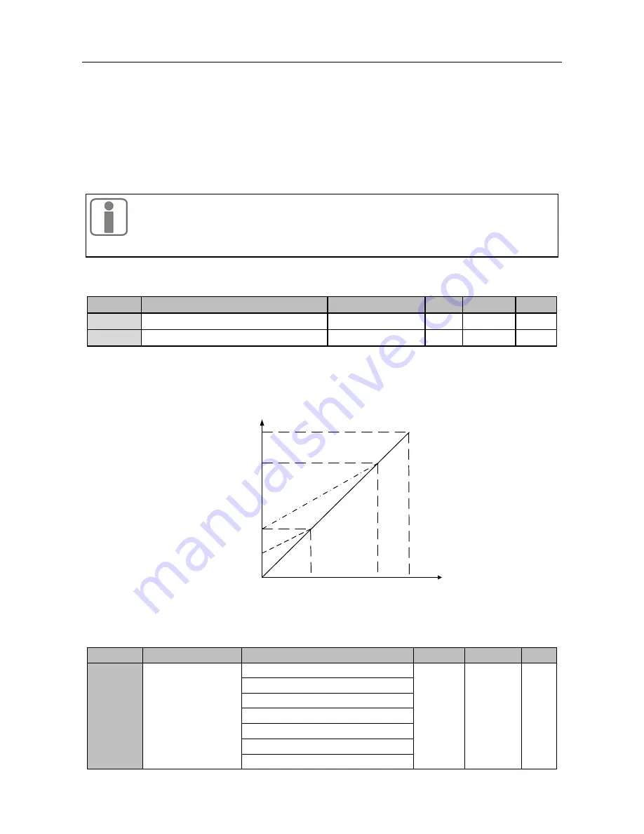
are to boost the low frequency torque of inverter, and to output high torque
at low frequency. The parameters cannot be set too big, otherwise, it will cause overcurrent.
If overcurrent fault is caused by the parameters, Fd-09 and Fd-10 can be set smaller.
See the Figure below for setting method:
Voltage
Frequency
Cut-off
Frequency of
Torque Boost
Fd-10
Torque Boost
Voltage Fd-09
100%
20%
100%
20%
10%
80%
80%
Remarks:
If Fd-09=10%, its low frequency voltage curve is shown as the bold dotted line.
8.14.3
Output Voltage Control in VF Separation Mode
No.
Function
Range
Unit
Default
Type
Fd-11
Output Voltage
Setting Mode in
VF Separation
Mode
0:Disabled
0
〇
1:Numeric Setting(FC-15)
2: VP Setting
3: VS Setting
4: VF Setting
5: IS Setting
6: IF Setting


