User Manual
EM303B General Purpose Inverter
130
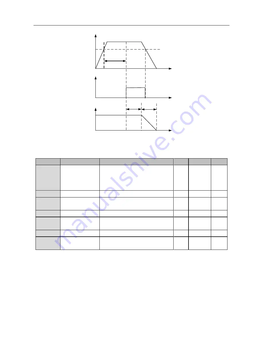
Overload Detection
Time
Time
Time
TIme
Stopping
Process
Run
Delay Stop
Time
Enabled
Inverter Status
Overload
Detection Start
Output Current
Overload
Detection Scale
Stop
Figure 7-23 Overload Pre-alarm Control Logic
8.9.2
Analog Output Scale
No.
Function
Range
Unit Default
Type
F7-04
Analog ADT
Options
0: VS 0.00
~
100.00%
1: IS 0.00
~
100.00%
2: VF 0.00
~
100.00%
3: IF 0.00
~
100.00%
2
〇
F7-05
Analog ADT1
0.00
~
100.00
%
20.00
●
F7-06
Analog ADT1
Hysteresis
0.00
~
100.00
(Monotonic decreasing is active)
%
5.00
●
F7-07
Analog ADT2
0.00
~
100.00
%
50.00
●
F7-08
Analog ADT2
Hysteresis
0.00
~
100.00
(Monotonic decreasing is active)
%
5.00
●
F7-09
Analog ADT3
0.00
~
100.00
%
80.00
●
F7-10
Analog ADT3
Hysteresis
0.00
~
100.00
(Monotonic decreasing is active)
%
5.00
●
Analog ADT function can monitor present analog value of analog input terminal and output
alarming signal.
Analog ADT Options
F7-04Analog ADT Options:
Options of analog ADT input terminals
F7-05Analog ADT1:
Analog ADT input scale. Select and adjust analog ADT input scale and
the input signal percentage of analog input terminal.
F7-06Analog ADT1Hysteresis:
Options of input scale hysteresis of analog ADT1.
For instance: If F7-04=2, F7-05=25.00, F7-06=5.00, and if input voltage of analog input
terminal VF>2.5V (10V4=2, F7-05=25.00, F7-06=5.00, and if input voltage of analog input


