User Manual
EM303B General Purpose Inverter
120
F5-22=1
Negative torque prohibited.
F5-13 and F5-23 will be blocked.
F5-22=0
Negative torque permitted.
F5-13 defines the torque output direction.
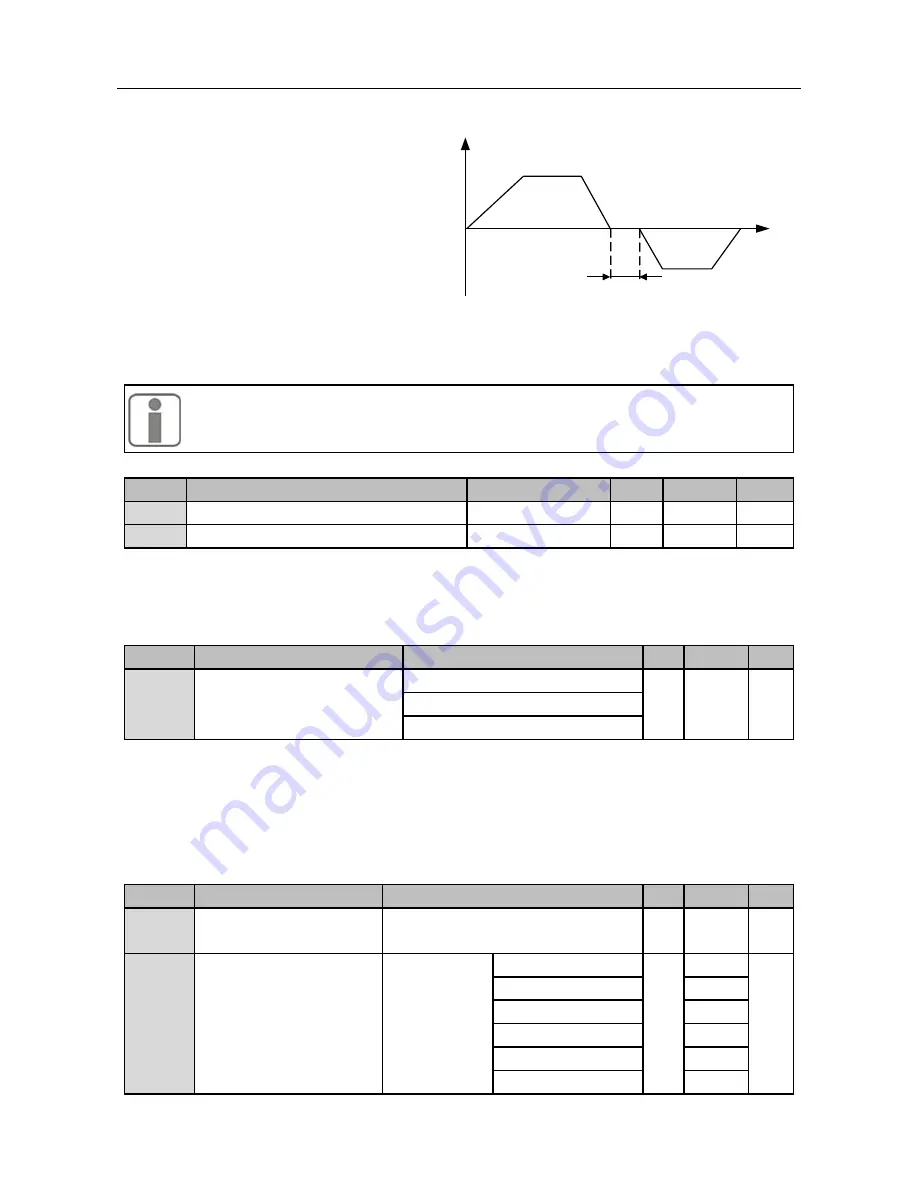
F5-23
is for setting the transit time at zero
output torque for the inverter in the process
of switching positive and negative torque.
See Figure 7-19.
The torque direction refers to the setting
direction of torque current, but not the
rotational direction of motor.
Figure 7-19
Deadband of Positive/Negative Torque
1.
The default forward direction of motor is the positive torque direction.
2.
If positive/negative torque switching is applied in torque program operation
mode, it cannot be switched by terminals.
No.
Function
Range
Unit Default Type
F5-24
Current Loop Gain ACR_P
0.00
~
10.00
%
0.40
●
F5-25
Current Loop Integration ACR_Ti
0.00
~
300.00
mS
10.00
●
F5-24 and F5-25
are PID regulator parameters of torque current, and will affect system
performance and stability directly. User does not need to change the defaults on general
conditions.
No.
Function
Range
Unit Default Type
F5-27
Control Mode at Zero
Frequency
0: Brake
2
〇
1: Normal
2: No output
F5-27
is for the control mode of inverter output frequency near zero frequency.
F5-27=0
Brake current at zero frequency can be set by F7-31, and it will make motor not be
driven by the load when the output frequency of inverter is zero frequency.
F5-27=1
Normal output control.
F5-27=2
There is no output near zero frequency. Motor can rotate freely.
No.
Function
Range
Unit Default Type
F5-26
Closed-loop Slip
Compensation Gain
50.00
~
200.00
% 100.00
●
F5-29
Excitation Gain Kd
100.00
~
600.00
0
~
9kW
%
100.00
●
9
~
30kW
150.00
30
~
55kW
200.00
55
~
75kW
300.00
75
~
110kW
400.00
110
~
400kW
500.00
Output Torque
Time
Deadband
Time


