background image


PFD Operation 

SkyView Pilot’s User Guide - Revision M  


4-23 

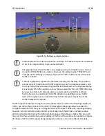
traffic targets that are shown to the left or right of the center of the attitude indicator are not 
directly ahead of you.  


Traffic displayed on the PFD page can be configured to include just Traffic 
Advisories (TA), all targets, or no targets. See the SkyView Installation Guide for 
information on how to configure how traffic is displayed.  

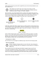
Note that traffic is not visually scaled for distance. In other words, targets always appear the 
same size on the Synthetic Vision depiction, no matter how far away they are. However, yellow 
Traffic Advisory Targets (threats) are displayed larger than the diamond shaped Proximity 
Advisory Targets and Non-Threat Targets to accentuate their increased importance. 


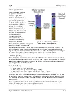
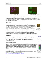
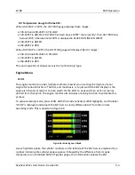
Figure 39 - Traffic Advisory on 

Synthetic Vision 


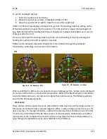
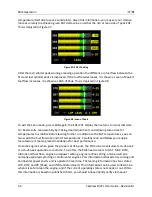
Figure 40 - Proximity Advisory on 

Synthetic Vision 


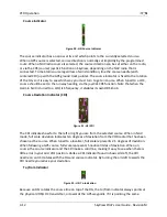
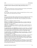
Figure 41 - Non Threat on Synthetic 

Vision 


Additionally, yellow Traffic Advisory targets contain a number within them that represents how 
far away they are (in miles, nautical miles, or kilometers, depending on your system setup) from 
your aircraft. The yellow Traffic Advisory target in Figure 38, for example, is 3 miles away, to the 
left, above, and descending. 


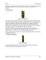
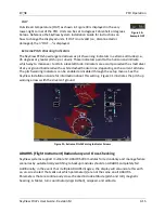
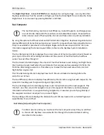
Figure 42 - Traffic Alert 

When a Traffic Advisory target is present, a yellow Traffic Alert Message appears on the PFD 
Page near the top of the IAS tape. Note that Traffic Advisory targets behind your aircraft will 
generate alerts. They can be seen on the Map Page, but will not be visible on the Synthetic 
Vision display as Synthetic Vision only shows the view in front of the aircraft. 

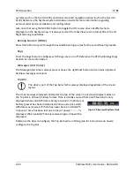
Bearing Source 1 (BRG 1) 

Press this button to cycle through the available bearing sources for the first bearing needle. 

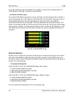
NAV Source (NAVSRC) 


SkyView’s Navigation Mapping Software course information can be displayed on 
the SkyView HSI display when it is navigating to an active waypoint. It is always the 
GPS

0

 source. 

Press this button to cycle the HSI through the different navigation data sources that are 
connected to the SkyView system (e.g., GPS 0-4 and NAV 1-4). Other than GPS0, which is 
sourced from SkyView’s own Navigation Mapping Software, these are all external navigation 
devices such as other portable GPS units (such as the Garmin 496), panel mounted IFR GPS 

Содержание SkyView SV-D1000

Страница 1: ...not approved for installation in type certificated aircraft Document 101321 012 Revision M For use with firmware version 5 1 January 2013 Copyright 2009 2013 by Dynon Avionics Inc Permission to print this this manual is granted to third parties ...

Страница 2: ......

Страница 3: ... electronic storage medium to be viewed for personal use provided that such electronic or printed copy of this manual or revision must contain the complete text of this copyright notice and provided further that any unauthorized commercial distribution of this manual or any revision hereto is strictly prohibited Information in this document is subject to change without notice Dynon Avionics reserv...

Страница 4: ...nded for use in type certificated aircraft at this time Dynon Avionics makes no claim as to the suitability of its products in connection with FAR 91 205 Dynon Avionics products incorporate a variety of precise sensitive electronics SkyView products do not contain any field user serviceable parts Units found to have been taken apart may not be eligible for repair under warranty Additionally once a...

Страница 5: ...GPS Source Section Added push to synchronize instructions for applicable bugs Moving Map Operation Chapter updates Added an important note regarding Moving Map requirements Added the GPS Source Section Added the Terrain Data Section Added the Aviation Data Section Corrected the Onscreen Alerts Section in the Alerts Chapter C May 2010 Document number changed to 101321 002 Minor style and grammar ch...

Страница 6: ...d information about G Meter Added information about new improved Navigation Mapping Software purchase licensing and operation H May 2011 Added description of enabling disabling extreme pitch warning indicators and Flight Path Marker Updated screen layout button labeling and figures Added information on Flight Planning Updated several of the figures that were no longer valid due to button and scree...

Страница 7: ...mber 2012 Updated Screen Layout Configuration section to add information about display swap mode and reversion mode Added information about DA calculation Added engine alert inhibit information Added information about normal display artifacts on power on Updated recommendation to have servos powered whenever SkyView is powered on Added description of take off position marking for trim widget Added...

Страница 8: ......

Страница 9: ... 5 3 SV D700 and SV D1000 Operation 3 1 Screen Synchronization 3 1 Display Bezel Layout 3 1 Joystick and Button Operation 3 2 Menu Navigation 3 4 Basic Display Operation Procedures 3 5 Screen Layout Configuration 3 7 4 PFD Operation 4 1 PFD Page Layout 4 1 PFD Symbology 4 2 ADAHRS Flight Instrument Redundancy and Cross Checking 4 15 PFD Menu 4 19 5 EMS Operation 5 1 Engine Page Layout 5 1 Rotax 91...

Страница 10: ...topilot Operation and Procedures 8 12 9 Messages and Alerts 9 1 Loss of Information 9 1 Message Caution and Warning Alerting System 9 1 Prompts Requiring Interaction 9 4 Audio Alerts 9 4 Messages Alerts and Audio Alert Details 9 5 10 Appendix A SkyView System Specifications 10 1 SV D700 and SV D1000 Quick Specifications 10 1 SV ADAHRS 20X Quick Specifications 10 2 SV ADSB 470 Quick Specifications ...

Страница 11: ...in any field user serviceable parts Units found to have been taken apart may not be eligible for repair under warranty Additionally once a Dynon Avionics unit is opened up it is not considered airworthy and must be serviced at the factory Dynon Avionics Product Registration Please take a moment to register your Dynon Avionics SkyView system at register dynonavionics com Registering your product wi...

Страница 12: ...non s Online Customer Forum is a resource for Dynon Avionics customers to discuss installation and operational issues relating to Dynon Avionics products The Forum is especially useful for pilots with uncommon aircraft or unusual installation issues For customers that cannot call Dynon Technical Support during our normal business hours the Forum is a convenient way to interact with Dynon Avionics ...

Страница 13: ...MS and Moving Map functions in more detail Power SkyView displays require between 10 and 30 volts DC for operation Approximate current consumption of a SkyView system at 12 and 24 volts DC is 3 5 amps and 1 8 amps respectively SkyView s robust power allows it to be powered on during engine start The current draw figures provided do not include Autopilot servo power draw as they receive power direc...

Страница 14: ...mentioned above Display The SV D700 display is a 7 inch 800 by 480 pixel 1200 nit TFT active matrix LCD screen The SV D1000 display is a 10 2 inch 1024 by 600 pixel 1350 nit TFT active matrix LCD screen SkyView displays utilize LED backlighting technology for increased lifespan more uniform brightness superior dimmability and reduced power consumption Displays are capable of automatic screen backl...

Страница 15: ...g parts These sensors include accelerometers which measure forces in all three directions rotational rate sensors which sense rotation about all three axes pressure transducers for measuring air data and magnetometers on all three axes for measuring magnetic heading These sensors form the core of Dynon s Air Data Attitude and Heading Reference System ADAHRS Table 2 describes which inputs and senso...

Страница 16: ...trim potentiometers external contacts and general purpose temperature sensors Certain configurations of the SV EMS 22X module also support 7 cylinder engines SV GPS 250 The SV GPS 250 GPS Receiver module is an optional externally mounted 5 Hz WAAS enabled GPS receiver designed specifically for use with SkyView It supplies GPS data in NMEA format and automatically sets the time on SkyView The SV GP...

Страница 17: ... and should power a typical SkyView system for at least 60 minutes If SkyView has switched to the backup battery due to a power loss in your aircraft it is advised that you land as soon as possible Autopilot Servos SV32 SV42 and SV52 servos enable SkyView to operate as an autopilot Navigation Mapping Software SV MAP 270 SkyView has a robust navigation mapping option that is enabled by a one time l...

Страница 18: ......

Страница 19: ... the system will synchronize important information between them Actions such as setting baro bugs engaging the autopilot or acknowledging warnings only need to be done on one display Some settings such as screen layout and map zoom level are not synchronized on purpose Firmware sensor configuration file sfg updates must also be done to each screen individually Navigation and obstacle databases may...

Страница 20: ...utton functionality is contextual based on what is onscreen and these labels show the user the current function For example the MAP label above joystick 2 in Figure 1 shows that manipulating that joystick will affect what the user can see on the Moving Map Page The set of button labels displayed immediately after the display turns on is referred to as the Main Menu Each SkyView display has an inte...

Страница 21: ...above it Joystick and Button Operation Example Some parameters may need to be adjusted using a joystick When setting values with the joystick each character symbol letter or digit must be selected and adjusted successively Figure 4 Adjusting Successive Characters with a Joystick In this example the first time you turn the joystick you toggle between the and symbols To change the succeeding charact...

Страница 22: ...sted menus before reaching a page A page or wizard is at the end of the chain and it is where the user can perform a specific action such as create a system software backup configure a SkyView network or set up the layout of the onscreen engine gauges Wizards employ easy to follow onscreen instructions For example SETUP MENU SYSTEM SETUP MEASUREMENT UNITS BAROMETER indicates entering the SETUP MEN...

Страница 23: ...depending on whether or not the aircraft is in flight This feature minimizes backup battery discharge when on the ground and master external power is shut off normally It also reduces pilot workload during an actual in flight power loss If the aircraft is not in flight SkyView displays the message POWERING DOWN IN xx SECONDS while counting down from 30 seconds During this countdown the menu displa...

Страница 24: ... to manual mode in the Setup Menu there will be no label If the display was set to automatic or external the label will toggle between MANUAL and AUTO or MANUAL and EXTERNAL respectively Reference the SkyView System Installation Guide for instructions on specifying the display s backlight brightness control method How to Enter the Joystick Function Menu Move a joystick up down left or right to ent...

Страница 25: ...EM SETUP TIME TIME ZONE OFFSET and adjust the time zone accordingly How to Configure the Top Bar The Top Bar is the strip across the top of the screen It displays textual information such as the clock and autopilot status Future software updates will use this space for information such as radio status Enter the Top Bar Setup Page to configure the Top Bar IN FLIGHT SETUP MENU FULL PAGE SETUP MENU o...

Страница 26: ...bove buttons for a few seconds to turn on that page and turn all others off with just one button push 3 Press LAYOUT to toggle between different layouts of the pages that are being displayed 4 Press BACK to finalize the layout and return to the Main Menu Swap Mode You may at times wish to swap the entire screen contents of your left and right displays without having to select and deselect each pag...

Страница 27: ...e pages automatically on the single remaining display should the other fail If reversion mode is enabled any one of the following layouts can be pre configured via SkyView setup procedures to be displayed when only one display remains powered on in a multi display system This behavior applies equally whether all but one display in your system has failed or if you turn on one SkyView display before...

Страница 28: ......

Страница 29: ...ynthetic Vision further requires valid GPS data The heading track altitude and vertical speed bugs are used to control the SkyView Autopilot PFD Page Layout The PFD Page as shown in Figure 7 displays important flight information and Synthetic Vision Figure 7 SkyView PFD The primary information shown on the PFD includes Synthetic Vision Airspeed Indicator with Airspeed Bug and Airspeed Trend Rate A...

Страница 30: ...titude vertical speed and heading or track bugs are used for autopilot control if Autopilot servos are installed Instructions for setting bugs are detailed in subsequent sections of this guide The airspeed altitude and vertical speed bugs are located above their respective tapes and the heading or track bug is located to the lower left of the compass rose directional gyro You can toggle the displa...

Страница 31: ...utopilot servos are installed the bugs used to control them are not configurable in this menu i e they are always on and have grayed out text to denote this as illustrated in Figure 11 Figure 11 Autopilot Control Bugs Grayed Out Airspeed Indicator The Airspeed Indicator is displayed on the left side of the PFD and incorporates an airspeed tape with a digital readout true airspeed TAS airspeed tren...

Страница 32: ...e acceleration is kept constant the airspeed will end up at the number indicated at the end of the trend line after 6 seconds have passed True airspeed TAS is digitally displayed at the bottom of the airspeed tape Airspeed Bug The airspeed bug is displayed in cyan on the airspeed tape and its associated digital readout is displayed at the top of the Airspeed Indicator To set the airspeed bug 1 Ent...

Страница 33: ...age in the In Flight Setup Menu IN FLIGHT SETUP MENU FLIGHT ANGLE PITCH ADJUST The pitch may be adjusted to a maximum of 20 degrees The extended zero pitch line features heading markers every 30 degrees to help maintain directional awareness when attention is being paid to the attitude indicator Attitude Rate Limit SkyView s ADAHRS will operate normally at rotational rates of up to 150 degrees per...

Страница 34: ...the marker can also be a valuable aide for avoiding terrain when used with Synthetic Vision The flight path marker can be enabled or disabled through the setup menus See the SkyView Installation Guide for information about this setting Several examples of Flight Path Marker behavior If the aircraft s nose is pitched up but the marker stays on the horizon this indicates that the aircraft is not cli...

Страница 35: ...e a 6 second altitude trend This means that if current rate of altitude change is kept constant the altitude will end up at the number indicated at the end of the trend line after 6 seconds have passed DA will display if an OAT probe is not connected to the SkyView ADAHRS module Since relative humidity is not readily available to SkyView in flight density altitude is calculated using an approximat...

Страница 36: ...to it You can synchronize the altitude bug with the current altitude by pressing and holding the ALT joystick to the left or right for 2 seconds If the autopilot is engaged and the altitude bug is changed to more than 100 feet away from the current altitude the autopilot enters vertical speed mode and the text in the Top Bar changes to VS ALT to indicate this new mode Reference the Autopilot Opera...

Страница 37: ...r of the pointer is the same as described above Vertical Speed Bug The vertical speed bug is displayed in cyan on the right side of the VSI tape and its associated digital readout is displayed at the top of the VSI This bug is used as an initial target for the pitch axis of the SkyView Autopilot when the pitch axis servo is installed and engaged in the vertical speed bug VS BUG mode of operation T...

Страница 38: ...isplayed as 33 The numeric display at the top of the compass rose indicates magnetic heading The turn rate indicator is displayed as a curved magenta bar along the top outside curve of the compass rose The bar grows in the direction that the aircraft is currently turning and is anchored at the arrow of the numeric display The minor tick marks to the immediate right and left of the numeric display ...

Страница 39: ... autopilot functionality symbology and operation information HSI Figure 18 HSI Example GPS Figure 19 HSI Example Localizer When a valid NAV or GPS source is connected to your SkyView system its data can be displayed on and around the DG in a standard HSI presentation Refer to the SkyView System Installation Guide for details on how to connect and configure these data sources The following sections...

Страница 40: ...rmin SL30 is tuned to a LOC ILS frequency it disables its own OBS knob Course Deviation Indicator CDI Figure 21 HSI CDI The CDI indicates how far to the left or right you are from the selected course When in NAV mode full scale deviation indicates ten degrees of deviation from the VOR radial that has been chosen as the course When tuned to a localizer full scale represents 2 5 degrees of deviation...

Страница 41: ...d There is also a textual information item for each bearing pointer that describes its source eg GPS0 NAV1 etc Each of the bearing pointers can be cycled between all available bearing sources by pressing BRG 1 or BRG2 in the PFD Menu Note that some radios such as the Garmin SL30 provide information about standby frequencies that can be loaded into bearing pointer locations These are only available...

Страница 42: ...d number is not displayed although the arrow is Note that due to a limitation in the SV GPS 250 hardware winds information will not be available above 415 knots ground speed if it is being used as the GPS source Slip Skid Ball The action of the slip skid ball simulates an analog slip skid ball and provides a visual representation of lateral acceleration When the ball is within the two vertical lin...

Страница 43: ...d with a white dashed horizon line depending on the current attitude The pitch warning indicators can be enabled or disabled through the setup menus See the SkyView Installation Guide for information about this setting Figure 31 illustrates the pitch up warning arrows with the slivers of ground Figure 31 Extreme Pitch Warning Indicator Arrows ADAHRS Flight Instrument Redundancy and Cross Checking ...

Страница 44: ...side by side The ADAHRS that was previously displayed on the PFD is labeled ACTIVE while the one that was not previously being displayed but which was being used as the cross check reference will be labeled as STANDBY Additionally the labels PRIMARY and ALTERNATE designate which ADAHRS is normally displayed when both are in agreement and neither is disabled Figure 33 ADAHRS Cross Check Comparison ...

Страница 45: ...te that only a single ADAHRS is available for use Figure 35 Single ADAHRS Mode Flag If after you ve entered the ADAHRS comparison screen you do not disable an ADAHRS a red warning and ADAHRS CROSS CHK ERROR alert will persist in the Message Alert Area above button 8 To go back to the ADAHRS comparison screen to disable an ADAHRS see the below instructions ADAHRS Source Selection and Configuration ...

Страница 46: ... in the event of a failure or problem with the primary ADAHRS However it normally won t be chosen for display on the PFD unless the primary ADAHRS has failed or has manually been disabled To change which ADAHRS is the PRIMARY ADAHRS highlight an ALTERNATE ADAHRS and press the PRIMARY button to elevate it to PRIMARY status To disable an ADAHRS until SkyView is next powered up simply highlight it wi...

Страница 47: ...s are being approached Instantaneous G information is also shown digitally in the center of the gauge Figure 36 G Meter on PFD The smaller digital numbers above and below the larger instantaneous G number are the maximum and minimum Gs that the aircraft has experienced since the G Meter was last reset Press PFD RESET G to manually reset the G Meter The G Meter may also be set up to automatically r...

Страница 48: ...epresented in sectional chart color variations which represent topographical elevations and water features Terrain is textured with a subtle checkerboard pattern to aid in identifying aircraft movement You may toggle the Synthetic Vision system off or on Press PFD on the Main Menu and then press SYNVIS Figure 37 contains an example SkyView Synthetic Vision view Figure 37 SkyView Synthetic Vision V...

Страница 49: ...own on Synthetic Vision if their highest point is within 1000 feet below your aircraft s GPS altitude If the highest point of an obstacle is within 100 feet below your current GPS altitude to anywhere above you it will be red If the highest point of the obstacle is between 100 and 1000 feet below your current GPS altitude the obstacle will be yellow This is the same color scheme used on the Map Pa...

Страница 50: ... updates such as those received by the SV XPNDR 26X may be anywhere from 2 12 seconds old due to radar latency and other technical factors Be sure to understand the traffic detection capabilities of your traffic device thoroughly so you understand how to best interpret the position of the traffic displayed on SkyView Traffic targets are displayed using the same symbols that are used on the Map Pag...

Страница 51: ...miles or kilometers depending on your system setup from your aircraft The yellow Traffic Advisory target in Figure 38 for example is 3 miles away to the left above and descending Figure 42 Traffic Alert When a Traffic Advisory target is present a yellow Traffic Alert Message appears on the PFD Page near the top of the IAS tape Note that Traffic Advisory targets behind your aircraft will generate a...

Страница 52: ...tion for more information Messages Text Varies The Message Alert Area is always present above the rightmost button and contains important SkyView messages and alerts Top Bar The clock is part of the Top Bar which is always displayed regardless of the screen layout The clock is always displayed centered at the top of the screen in all screen display modes on the Top Bar in 24 hour military format T...

Страница 53: ... been configured during installation The appearance of the 20 and 50 Engine Pages are not scaled down versions of the 100 Engine Page They are unique layouts and must be laid out individually The Engine Page as shown in Figure 44 displays important engine parameters acquired using an SV EMS 220 module its sensors and other advanced engine monitoring features Figure 44 Example 50 SkyView Engine Pag...

Страница 54: ...presentation allows all CHTs and EGTs to be displayed in a way that affords quick comparison of their values whether raw data or a graphical comparison is preferred Figure 45 Combined CHT EGT Gauge Rotax 912 Behavior SkyView can be configured to adjust the oil temperature and tachometer gauges for the Rotax 912 engine dynamically to reflect limitations that Rotax specifies for that engine When thi...

Страница 55: ...to assist you in setting the mixture of your engine for various functions The first and most basic is to just watch the EGT display as the engine is richened or leaned You can watch for the EGTs to peak and then richen or lean as desired from that point The engine monitor also includes a leaning function to automate this process To activate leaning mode press LEAN With this mode activated LEAN hig...

Страница 56: ...me for temperatures to stabilize before leaning further In addition to the EGT temperatures you can also watch the fuel flow rate and CHT temperatures Carefully read and follow your engine manufacturer s leaning recommendations for best performance On some engines when given the proper set of inputs the EMS can also calculate lean of peak or rich of peak operation in real time To do this the EMS n...

Страница 57: ... above 15 PSI or the engine is above 200 RPM It essentially runs when the engine does The Engine Run Timer labeled RUN TIME when displayed on an Engine Page is a Hobbs style timer that records the time your engine has been running during your current flight It resets the first time the engine is started after SkyView is powered on This allows you to view your previous flight s Engine Run Time any ...

Страница 58: ...fuel flow sensor has seen flow through it The Fuel Used info item displays the amount of fuel that has been used during your flight Note that Fuel Used resets itself when the unit detects that oil pressure has exceeded 15 PSI for the first time after being powered on This allows you to view the fuel used value from your last flight before engine start The Time Remaining info item displays how much...

Страница 59: ... fuel This is limited to adjustments that set the Total Fuel to between 0 and the total fuel capacity as defined in the Setup Menu Press FULL to have SkyView recall a previously programmed amount of fuel which represents the full fuel load of the aircraft See the SkyView System Installation Guide for information about how to set this value Press PRESET to have SkyView recall a previously programme...

Страница 60: ...ed That license is applied to only one display but that display stores the license information for the entire system In normal use license information is shared with all displays connected via SkyView Network to allow the VP X features to be operated on any display in the system Information about purchasing a license installing a VP X license on a SkyView system and configuring SkyView to properly...

Страница 61: ...be visible on the display that you are trying to access the VP X page on The ENGINE page can be toggled on and off on a display by pressing MAIN MENU SCREEN EMS PG The Engine Page dynamically resizes to accommodate the VP X page alongside of it If all of the PFD Engine and Map Pages were being displayed when the VP X page is toggled on the Map Page will automatically be removed to accommodate the ...

Страница 62: ...ects fault in a circuit system overvoltage system overcurrent and other failures Look at all elements on the VP X page to identify the specific error Power Circuit List The bottom of the VP X page depicts the status of all circuits that have been configured and are enabled in the VP X setup process The center column displays the name of the circuit The column to the left of the circuit name is bla...

Страница 63: ...rim movement o For Flaps Moves flaps up or down as described in the VP X documentation Depending on the VP X configuration a single quick press of the UP or DOWN button may move the flaps to a preconfigured angle or notch of flaps Or it may only move the flaps momentarily This button can be held down for continuous trim movement LEFT RIGHT buttons o For Roll Trim Moves the roll trim left or right ...

Страница 64: ......

Страница 65: ...UT messages via its 1090ES capability The SV XPNDR 26X transponder is controlled using the SkyView s on screen menu system This allows the transponder to be mounted separately from the instrument panel and reduces the amount of panel space taken by the transponder SkyView also provides pressure altitude directly to the transponder eliminating the need for a separate altitude encoder Transponder St...

Страница 66: ...ntire transponder status area Indicates an error either with the transponder itself or in the communication between the transponder module and SkyView The transponder is not responding to interrogations Check the wiring and settings between the transponder module and SkyView if you are authorized to maintain your aircraft Contact Dynon Technical Support for further assistance Reply Status The repl...

Страница 67: ...nder in standby mode ON Press to set the transponder to respond to all interrogations but with altitude reporting suppressed When active the ON button will remain highlighted in this menu and ON is annunciated in the transponder status area in the Top Bar When the transponder is on in this mode pressing ON again will turn put the transponder in standby mode ALT Press to set the transponder to resp...

Страница 68: ...stalled and working it automatically provides ADS B output at the appropriate integrity level for the GPS signal being used ADS B OUT transmissions that meet the 2020 FAA ADS B equipment mandate require that a TSO 146c GPS signal be directly provided from the GPS to a capable ADS B device such as the SV XPNDR 26X For this purpose a dedicated serial input is provided on the SV XPNDR 26X module that...

Страница 69: ... free trial of the Navigation Mapping Software that allows you to try it out before you purchase it After the 30 flight hour free trial period expires the MAP menu and all navigation mapping and other features that are displayed on the map page such as weather will cease to be available until a Navigation Mapping Software License is activated Additionally all other features that rely on aviation o...

Страница 70: ...er is only checked on boot If it expires during a flight the Navigation Mapping Software will remain available for the remainder of that flight Features Overview Once licensed the following features are enabled as long as SkyView has the appropriate high resolution terrain database installed for the region of the world that you are flying in and an aviation database installed Use of MAP menu and f...

Страница 71: ...rom Dynon Avionics Aviation data Airports nav aids airspace airport information etc Available for free for US customers from Dynon Jeppesen and PocketFMS data available for all other customers worldwide Obstacles data Available for free for US customers from Dynon Jeppesen and PocketFMS data available for all other customers worldwide Basemap Cultural Data Database is available for free for all cu...

Страница 72: ... with Obstacles and Visual Reporting Points The PocketFMS Foundation has been providing worldwide aeronautical data since 2003 AeroData is professionally maintained and updated for SkyView every 28 days and is available as a yearly subscription including obstacles for 119 Coverage encompasses Europe North America including Canada Australia and New Zealand It includes Aviation data including visual...

Страница 73: ... the display s USB sockets 3 Go to the Load Files Wizard SETUP MENU SYSTEM SOFTWARE LOAD FILES 4 Select a file and press LOAD to load the file onto the system 5 Exit Setup 6 In SkyView systems that have more than one display aviation and obstacle databases are automatically synchronized to other connected displays provided that those displays are connected via Ethernet If they are and you have the...

Страница 74: ...vice to work in a SkyView system This guide assumes these steps have been properly executed You should be familiar with the information in the SkyView System Installation Guide regarding this topic SkyView s Moving Map display depends on the system having a valid GPS source In the event of the failure of the primary GPS source used to display the Moving Map SkyView will automatically use other ava...

Страница 75: ...nd bodies of water with Terrain Proximity Alerting Aircraft Icon with Ground Track Line Distance Circle and Range Heading Arc Current Ground Track Heading Bug True North Marker Configurable Info Items Examples include GPS Ground Speed SPEED GPS Altitude ALTITUDE Distance to Waypoint DTW and Bearing to Waypoint BTW Course line only displayed when actively navigating to an aviation waypoint Airports...

Страница 76: ...w the aircraft s current altitude Red terrain default setting is within 100 feet below or above the aircraft s current altitude Aircraft Icon with Ground Track Line The aircraft icon as shown in Figure 55 represents your aircraft on the Moving Map Page The ground track line represents the projected ground track of the aircraft The aircraft icon in the figure below denotes that SkyView has obtained...

Страница 77: ...f the right side of the Map Page near the Distance Circle Turn the MAP joystick to zoom in and zoom out Zoom level can be adjusted between 0 3 and 1200 nautical miles Units can be set to miles nautical miles or kilometers Reference the SkyView System Installation Guide instructions on how to change the displayed units The heading arc is explained in the next section Ground Track Arc Current Ground...

Страница 78: ... will be white Figure 58 Current Ground Track The heading bug as shown in Figure 59 is represented with a cyan marker When moving the heading bug a cyan colored lubber line that extends from the aircraft to the bug is displayed as well Reference the Heading Track Bug Section for instructions on how to adjust the heading bug Figure 59 Heading Bug The north marker as shown in Figure 60 is represente...

Страница 79: ...e Moving Map display whenever a flight plan has been activated The magenta line corresponds to the current leg of the Flight Plan and subsequent legs are shown in white Legs prior to the current leg are not shown See the Flight Planning section of this guide for more information about creating and working with flight plans Figure 62 Flight Plan Legs ...

Страница 80: ...tly between the tips of group icons Obstacles are only shown on the Moving Map if their highest point is within 1000 feet below your aircraft s GPS altitude If the highest point of an obstacle is within 100 feet below your current GPS altitude to anywhere above you it will be red If the highest point of the obstacle is between 100 and 1000 feet below your current GPS altitude the obstacle will be ...

Страница 81: ... Table 6 The floors and ceilings of airspaces are shown within each airspace segment in the familiar sectional style notation Airspace Type Color Example Class A Solid orange with interior shading Not depicted in the US where all airspace above FL180 is Class A Class B Solid dark blue with interior shading Class C Solid dark magenta with interior shading Class D Dashed light blue ...

Страница 82: ...as that extend to the surface in US depictions Solid green with interior shading Restricted and Prohibited Solid orange with ticks marks Warning Caution Training and Alert Areas Yellow tick marks not solid Military Operations Area MOA Solid purple with ticks marks TMA MTMA Terminal Control Area Solid dark blue with interior shading ...

Страница 83: ...e CTA Control Area Solid purple CTR Control Zone Blue orange solid Mode C Veil Not shown None Upcoming Temporary Flight Restriction TFR Yellow Active Temporary Flight Restriction TFR Red Stadium Temporary Flight Restriction TFR Orange Air Defense Identification Zone ADIZ Not shown None Table 6 Airspace Colors ...

Страница 84: ...g that shows the orientation of the VOR s radials Fixes SkyView represents a fix using a light blue triangle with a six character name underneath as shown in Figure 66 Figure 66 Moving Map Fix NDBs and Markers SkyView represents NDBs using the same symbols that are used on a sectional chart with a two three character name underneath as shown in Figure 67 NDB Outer Marker Figure 67 Moving Map NDBs ...

Страница 85: ...primary runway direction indicated Private Airport Airport With Control Tower blue Airport with services ticks at edges Seaplane Base Public Airport no hard surface runway Figure 69 Moving Map Airport Example Icons User Waypoints SkyView supports a diverse set of icons that can be used to identify User Waypoints A few of the many available icons are shown here See the SkyView User Waypoints sectio...

Страница 86: ...ter These preferences are located in MAIN MENU MAP MENU MAP ITEMS Use these settings to specify the highest zoom level that the various features are displayed Regardless of the max zoom level setting for each of the airspace types that can be adjusted in the MAP ITEMS menu SkyView will only display airspace segments at and below the altitude chosen in feet in the AIRSPACES BELOW option Traffic Whe...

Страница 87: ...r responsibility to see and avoid traffic Traffic is displayed as reported by the device sending it to SkyView The precision and accuracy of the location of traffic targets may vary from device to device and this may impact how accurately the position is represented on the SkyView display For example TIS traffic updates such as those received by the SV XPNDR 26X may be anywhere from 2 12 seconds o...

Страница 88: ... ADS B system will rebroadcast all of the 1090ES ADS B equipped targets onto the 978 MHz band for your benefit 2 Radar targets Any targets that the FAA s radar system is aware of via approach center and other radar facilities The end result your aircraft sees the vast majority of the aircraft that can possibly be a factor Since SkyView participates in the ADS B system via the SV XPNDR 26X s ADS B ...

Страница 89: ...ch as the SV XPNDR 26X will not show a vertical speed component unless it is greater than 500 fpm If available from the traffic device an orange vector arrow that starts at the target and points in the aircraft s direction of travel This length of the vector represents where the aircraft is expected to be in one minute based on its current trajectory o The data received by a TIS device such as the...

Страница 90: ...oom level Note that the orange vector arrow may not be visible when a Traffic Advisory is off the screen Proximity Advisory Targets Figure 74 Proximity Advisory Proximity have less of a chance of being a factor based on their position but are not a Traffic Advisory because they are not converging with your aircraft within the next 30 seconds A Proximity Advisory symbol is shown on the map when it ...

Страница 91: ...icture PARTIAL ADS B FLARM and Zaon only Sources that are passive traffic detectors such as the Zaon XRX and FLARM devices are not able to directly interrogate aircraft or utilize the ADS B system to qualify the completeness of the traffic picture around your aircraft PARTIAL is annunciated to indicate that the traffic picture may not include the entirety of the actual traffic environment around y...

Страница 92: ...age near the top of the IAS tape and the Map Page lower right whenever there are Traffic Advisory Targets present MAP Menu The MAP Menu is accessible from the Main Menu by pressing MAIN MENU MAP BACK Press BACK to return to the Main Menu The Direct To button brings up the Info page when it is pushed in the Map Menu It will also instantly start navigation to a waypoint when it is pushed when an air...

Страница 93: ...odify a Flight Plan Reference the Flight Planning section of this guide for details ADD FPL This button appears on the MAP Menu when the Nearest Info or window is open and an airport navaid or other waypoint is selected Press ADD FPL to insert the selected item into the Flight Plan Reference the Flight Planning section of this guide for more details TERRAIN WEATHER WX TERR This button cycles betwe...

Страница 94: ...ures SkyView s Navigation Mapping Software course information can be displayed on the SkyView PFD s HSI display when it is navigating to an active waypoint It is always the GPS0 source Navigation Methods SkyView supports two types of navigation Direct To navigation lets you quickly fly directly to a waypoint by pushing the button whenever it is displayed Additionally SkyView offers robust Flight P...

Страница 95: ...elect the next character and continue until the desired facility is shown Alternatively if you move the CURSR joystick left after the first press of the INFO button you can choose from the most recently used and viewed airports and navaids under the RECENT tab Press to navigate directly to the currently displayed or highlighted airport or navaid or ADD FPL to add it as a waypoint in a Flight Plan ...

Страница 96: ...nob up down to highlight different items in the list Once the desired facility is shown press INFO for more information about it to navigate directly to it or ADD FPL to add it as a waypoint in a Flight Plan Detailed Facility Information When an airport is displayed in the Info window after the INFO button is pressed detailed information about the selected facility is displayed Information is arra...

Страница 97: ...9 airports have multiple runways listed under the RWY tab Once the RWY tab is selected different runway information can be displayed by turning or moving the CURSR knob up down You may press ADD FPL from the info window to add the displayed facility as a waypoint to the Flight Plan ...

Страница 98: ...SV MAP 270 Navigation Mapping Software 7 30 SkyView Pilot s User Guide Revision M Figure 81 Airport Info Figure 82 Airport Comms Info Figure 83 Airport Runway Info Figure 84 Airport Remarks ...

Страница 99: ...a direct course from your present position press in either the Nearest or Info windows when the desired airport or navaid is highlighted This instantly makes the selected item an active waypoint that SkyView is navigating to and automatically closes the Info or Nearest window Press from the Map Page to bring up the Info window that allows you to search for a waypoint by identifier name or city You...

Страница 100: ...s deactivated by the use of the feature it will be reloaded but will not be activated Alternatively if you had a flight plan that was previously suspended through the use of the feature you can use FPL RSM FLP to resume flight plan to reactivate that flight plan and cancel the operation Map Panning with the Map Pointer Move the MAP joystick up down left or right or in any diagonal direction to cau...

Страница 101: ...aring from the aircraft position to the Map Pointer The estimated time in minutes that it would take to reach the Map Pointer if you were to fly directly to it at the current GPS ground speed Figure 87 Map Pointer Information Bar When in Map Panning Mode pressing will cause a temporary MAP POINTER waypoint to be created that allows you to navigate Direct To the location that you are pointing at wi...

Страница 102: ... USB memory stick causes the currently loaded Flight Plan if any to be overwritten When the feature is used the current Flight Plan is temporarily overwritten by the action When the is cancelled that previous Flight Plan is reloaded but navigation is not automatically reactivated To reactivate the reloaded Flight Plan press the ACTIVATE button in the MAP Menu There are two types of leg transitions...

Страница 103: ...ure 88 illustrates the following items Waypoint List The list of waypoints making up the current Flight Plan Waypoint Icons The icon that would be shown on the Map Page for the waypoint is shown to the left of each waypoint in the Flight Plan Active Leg Icon The active leg of the Flight Plan is depicted by a hooked arrow from origin waypoint to the destination waypoint if the leg is point to point...

Страница 104: ... items to proceed NRST and INFO Press these to bring up the Nearest or Info windows The Flight Plan window will be exited BACK Press to exit the FPL MENU if open or press to exit the Flight Plan window ACTIVATE RSM FPL Press to activate deactivate the current Flight Plan The button is highlighted when a Flight Plan is active If a Flight Plan is interrupted by a that Flight Plan is reloaded after t...

Страница 105: ...e Flight Plan and activate it An existing Flight Plan will be overwritten The IMPORT Tab is exited and ACTIVE tab is redisplayed FPL MENU Overview The following figures show the FPL MENU To select an operation from the menu scroll up and down by turning the joystick or moving it up down Move the joystick left to exit the FPL MENU or move the joystick knob right to accept initiate the selected oper...

Страница 106: ...e flight plan WAYPOINT Select to initiate a Direct To leg to the selected waypoint and execute the remainder of the Flight Plan as normal ACTIVATE LEG Select to make the leg that ends at the selected waypoint the current leg TOGGLE OVERFLY Select to toggle the transition type at the selected waypoint from overfly to flyby or vice versa An OF icon next to the waypoint in the flight plan denotes tha...

Страница 107: ...r when MAP MENU ADD POINT TO FPL is used in map panning mode the selected waypoint is highlighted within the Flight Plan Turn the knob or move the joystick up down to choose the precise place in the Flight Plan that you would like to insert the waypoint Then press INSERT to confirm your placement The waypoint will be added at the cursor location If you insert a waypoint via the ADD FPL button the ...

Страница 108: ... want to navigate to press FPL MENU select WAYPOINT and confirm Guidance will be provided directly to the selected waypoint and to the remaining legs in the Flight Plan after that Similarly use the ACTIVATE LEG option in the FPL MENU to skip to the leg that ends with the highlighted waypoints In contrast to the WAYPOINT option ACTIVATE LEG does not use your aircraft s current position to generate ...

Страница 109: ...ipulate and import export User Waypoints A User Waypoint is a point on the map which shows up as an icon of your choosing Like other airports or navaids they can be used in flight plans as Direct To navigation waypoints or can simply be used visually on the Map Page to help you navigate Creating Waypoints From the Map Menu select MAIN MENU MAP MENU CREATE WAYPOINT to enter the user waypoint creati...

Страница 110: ...e changed with the cursor if you would like to create a waypoint based on other coordinates Altitude Not currently used for navigation purposes but is shown on the Info page Icon Choose from a variety of aviation style icons pushpins buildings etc Press SAVE to save the waypoint User waypoints will automatically be synchronized across multiple SkyView displays in the aircraft provided they are con...

Страница 111: ...nts database will be distributed and synchronized between all displays If your displays are not connected via Ethernet you will need to import this file on each display separately See the SkyView Installation Guide for more details about this connection Clear Database Deletes all user waypoints currently stored in SkyView User Waypoints CSV comma separated values File Format An easy way to obtain ...

Страница 112: ...e respected as the field delineator and everything after the first comma will not be imported this procedure is not necessary when using a spreadsheet program such as excel The following is an actual example of a waypoint file It contains two points Dynon Avionics offices and Mount Rushmore The first line in a waypoint file is considered header information It is not counted as a waypoint The below...

Страница 113: ...n the NRST page Map Items Use these settings to specify the largest zoom level that the various features are displayed Info Items Use these settings to display up to 10 informational items along the left and right sides of the Map Page Items available for display include o Bearing to Waypoint o Cross Track This is the shortest possible distance that can possibly be traveled that will put you back ...

Страница 114: ...GPS ground speed is 25 knots your Vno speed setting is used for so that you can see approximate travel times while on the ground o GPS Altitude The current GPS altitude Note that this is MSL not AGL This number may differ significantly from your barometric indicated altimeter due to variations in the GPS data model GPS accuracy and nonstandard variations in outside pressure o Ground Speed o Next C...

Страница 115: ...images are actually ALWAYS older than the age indicated on the display In extreme cases this can mean that the images you see on SkyView may be 15 20 minutes older than the age indicated by SkyView See http www ntsb gov doclib safetyalerts SA_017 pdf for further information about this phenomenon Never rely on NEXRAD imagery to try to squeeze through a weather system Often deadly turbulence and win...

Страница 116: ...ntinental US CONUS The FAA s ADS B system transmits both of these periodically limiting the high resolution regional weather imagery to your locale to preserve available ADS B data link bandwidth SkyView presents all of this data seamlessly TFRs Temporary Flight Restrictions SkyView can graphically depict FAA temporary flight restrictions TFRs that restrict GA aircraft movement Weather options Go ...

Страница 117: ... Figure 99 Map Page Terrain View no Weather WEATHER Terrain is not depicted This allows the NEXRAD weather TFR layers to be displayed against a dark background for maximum legibility Other databases aviation obstacles base map etc are still displayed Figure 100 Map Page Weather View ...

Страница 118: ...tion Purple Black Green Yellow Orange Red Dark Red Magenta No Data Trace Light Moderate Heavy Heavy Extreme Extreme Table 10 NEXRAD Precipitation Legend NEXRAD Data Coverage In some circumstances geographic areas may not have NEXRAD imagery available This may be the case if Data is not available for the area because there is no NEXRAD coverage in the locale This can be observed in the areas surrou...

Страница 119: ... SkyView ADS B Receiver Status Data Age A status data block in the lower left corner of the map page contains information about both the ADS B Receiver s state as well as age of the weather data that was last received by the ADS B receiver Figure 104 Data Current Figure 105 Data Stale Figure 106 Data Expired Figure 107 ADS B Receiver Not Found Information contained within this data block includes ...

Страница 120: ...FO pages Additionally a summary of the nearest METAR weather reports for airports that report METAR information can be found in the NRST list Nearest Weather The MAIN MENU MAP NRST window will contain a WX weather tab whenever weather information is available to SkyView Figure 108 Nearest WX The flight category below the airport identifier indicates the weather conditions at the airport Possible f...

Страница 121: ...AR Decoded Figure 110 TAF Decoded Figure 111 METAR TAF RAW Flight categories for METAR and TAF reports are the same as described in the above Nearest Weather section The age of METARs and TAFs are explicitly stated via the OBSERVED line of the report Reports are considered METAR o Current white Data is between 0 and 70 minutes old o Stale yellow Data is between 70 and 120 minutes old o Expired red...

Страница 122: ...ed off and are listed as a separate option under MAP MENU MAP ITEMS TFR AIRSPACE STADIUM Due to limitations in the way that the FAA currently transmits TFR information via ADS B many TFRs including but not limited to such as VIP movement Security Hazard Presidential movement cannot be depicted by SkyView Therefore pilots should not rely on SkyView TFR depiction as an authoritative source of TFRs M...

Страница 123: ...ook for the presence of powered up servos even when the autopilot is disengaged and will show an error condition if they are not seen Therefore Dynon Avionics recommends that the servos receiving power whenever SkyView is powered on in routine operation When the servos are receiving power but the autopilot is not engaged the servos draw negligible power Finally in the unlikely event of an internal...

Страница 124: ...ted by the maximum bank angle setting if the turn rate requested by the autopilot requires a higher bank angle than configured Regardless of the mode the autopilot turns the aircraft the direction that results in the shortest turn required to achieve the target heading or track when in HDG or TRK mode respectively Vertical Autopilot Functionality This section summarizes the vertical functionality ...

Страница 125: ...during initial autopilot installation and configuration It will also not allow vertical acceleration to exceed 2G and 1G If these airspeed or G limits are hit the autopilot will not pull or push on the pitch axis in a way that would exceed these limits Control Wheel Steering Functionality Refer to the Control Wheel Steering Section near the end of this chapter Top Bar Autopilot Symbology The SkyVi...

Страница 126: ...ses AP text and roll and pitch axes engagement arrows and does not address specific roll and pitch information It is best viewed in full color AP Text and Roll and Pitch Arrow Appearance AP Roll Axis State AP Pitch Axis State DISENGAGED DISENGAGED ENGAGED DISENGAGED DISENGAGED ENGAGED ENGAGED ENGAGED RECENTLY DISENGAGED DISENGAGED DISENGAGED RECENTLY DISENGAGED RECENTLY DISENGAGED ENGAGED ENGAGED ...

Страница 127: ...te numerical value to the right of TRK as shown in Figure 119 is the target ground track Note that the AP text and roll arrow are absent from the figure indicating that the roll axis is disengaged Figure 119 Roll Axis Example Track mode 90 target ground track heading disengaged A track value in blue denotes that the roll axis is engaged and is turning toward or holding that track as shown in Figur...

Страница 128: ...e 125 Roll Axis Example Navigation mode GPS Steering engaged Roll Slip You may see this during periods of turbulence or if the strength of the servo is not sufficient to actuate the control surface If slipping occurs on the roll servo SkyView displays a slip warning as illustrated in Figure 126 Figure 126 Roll Axis Slip Indicator Reference the SkyView System Installation Guide for more information...

Страница 129: ...ormation in the Top Bar Altitude Mode ALT is displayed in the pitch axis information area when the pitch axis is armed or engaged in altitude mode The value to the right of ALT is either the target or current altitude Note that the altitude value in the Top Bar is displayed without units The unit of measurement for the value in the Top Bar is either in feet or meters depending on the chosen unit s...

Страница 130: ...ot is disengaged If trim is needed the altitude target value or future state will be replaced by and then alternate between the word TRIM and either an up or down symbol i e or To eliminate the excessive trim forces that the autopilot is trying to overcome trim the nose of the aircraft in the direction the arrow indicates Adjust the trim in small increments and wait a few seconds between adjustmen...

Страница 131: ...e 135 Pitch Axis Example AP Menu Error Message A pitch error occurs when the servo cannot be engaged It may indicate that the servo is unpowered has not been configured or has failed Consult the SkyView System Installation Guide for information regarding installation configuration and calibration of SkyView servos Pitch Axis Information Top Bar Summary Table 13 summarizes the pitch axis informatio...

Страница 132: ...he autopilot cannot pitch the aircraft down without going above the maximum airspeed SkyView displays REDUCE POWER Likewise when the autopilot is engaged and aircraft airspeed drops below the minimum the autopilot enters an airspeed hold mode pitching the aircraft down to prevent dropping below the minimum airspeed When the aircraft s altitude drops below the target ALT bug and the autopilot canno...

Страница 133: ...ode NAV indicates the roll axis is armed in navigation mode Two visual indicators are used to denote the state of the roll axis text and the appearance of the button label An ON suffix means the roll axis is engaged An OFF suffix denotes that the roll axis is disengaged When engaged the roll axis button label is highlighted e g You may engage or disengage the roll axis by pressing button 2 Roll Ax...

Страница 134: ...ith the current altitude when the pitch axis is engaged Pressing SYNC does not exit the Pitch Axis Mode Menu 180 Press 180 to initiate an autopilot controlled 180 degree turn from the current heading while maintaining the current altitude The autopilot will turn the aircraft to the left with the pitch axis in altitude hold mode Messages Text Varies The Message Alert Area is always present above th...

Страница 135: ...K to return to the AP Menu if you only pressed SYNC If you toggle SYNC while the pitch axis is disengaged the Top Bar altitude target will display HOLD in white text When the pitch axis is engaged the autopilot synchronizes the altitude bug with the current altitude the target text in the Top Bar turns blue and displays the bug setting and the autopilot holds the altitude If the pitch axis is alre...

Страница 136: ...servos are waiting for the Disengage CWS button to be released before engaging Once the button is released the autopilot engages in the mode s that are indicated in the AP Menu AP Top Bar status area When the autopilot is engaged this way the SYNC behaviors described in the sections above are also observed in the same way that they would be if you engaged each axis from the AP Menu buttons This is...

Страница 137: ...e the maximum and minimum limits configured for the pitch axis during installation releasing the Disengage CWS Button will not re engage the autopilot The autopilot can only be re engaged when airspeed is within the acceptable range How to Change Autopilot Target Heading Track or Altitude The SkyView Autopilot uses heading or track vertical speed and altitude bugs as targets during operation If th...

Страница 138: ......

Страница 139: ...a source such as an EMS module fails or a red X may overlay a single widget if a single engine sensor fails or is not connected For example the PFD would look like Figure 141 if all ADAHRS in the system fail Figure 141 Example SkyView Failure Message Caution and Warning Alerting System Message Notification Area The area directly above the rightmost button button 8 is the Message Notification Area ...

Страница 140: ...ll present Solid No active alerts or messages no color Table 14 Notification Types Whenever a new alert or message is generated the Message Notification Area will flash to provide a clear visual indication that there are unviewed messages or alerts that have not yet been seen and acknowledged When alert conditions are present but they have been acknowledged by viewing them the Message Notification...

Страница 141: ...under the Message Notification Area to display the Message Window Figure 143 Message Window The Message Window prioritizes alerts and messages from top to bottom in the following order Red warning alerts Yellow caution alerts White advisory messages Additionally messages are further sorted in the order in which they occur with the newest being higher Messages that are highlighted indicate that the...

Страница 142: ... to exist or may extinguish with acknowledgement depending on how SkyView is configured Instructions for adjusting this behavior are discussed in the SkyView System Installation Guide If new messages or alerts are triggered while the Message Window is being displayed they are not immediately displayed and will not be seen until the NEXT time the Message Window is displayed This reduces visual nois...

Страница 143: ...perature Engine Speed Engine Parameter HIGH or LOW Engine Parameter High or Low High or Low is not be displayed for all parameters Engine Alerts can be optionally configured to be inhibited before engine start or 5 minutes whichever comes first See the SkyView Installation Guide for details Warning ADAHRS CAL CORRUPT Contact Dynon for assistance Engine Monitor VP X channel name FAULT VP X channel ...

Страница 144: ...itude information Attitude may be degraded Caution ADAHRS CAL OLD Contact Dynon Avionics for assistance Caution AP BROKEN DISCONNECT Autopilot disconnect switch wire is broken Caution XPNDR ALT ENCODER FAIL Altitude is not being sent to the SV XPNDR 26X because it is not available from its nominal barometric altitude source Caution ADAHRS VIBRATION The ADAHRS has detected vibration that will affec...

Страница 145: ...fic None n a A new traffic advisory target has been identified Note that this audio alert is suppressed when not in flight to reduce nuisance alerts Other visual traffic alert indications persist however Autopilot Mode None n a The autopilot roll mode has changed since it was engaged Autopilot Disconnect None n a The roll or pitch autopilot axis has disconnected Trim Up None n a The autopilot requ...

Страница 146: ...stem that is equipped with two of them There is little you can do to troubleshoot such an issue in flight should it occur However you should exercise the same precautions you would exercise if you did not have backup flight instruments If you are flying in IMC especially you should consider making a precautionary landing as soon as possible Since a STANDBY NETWORK ERROR may be either a discrete si...

Страница 147: ... 0 7 amps with battery Connections 1 37 pin D sub male connector 2 9 pin D sub male connector 2 USB 2 0 A series jacks 1 RJ45 Ethernet jack SV D700 Screen Type Thin film transistor active matrix LCD Brightness 1200 nit light emitting diode Size 7 0 diagonal 178 mm widescreen Resolution 800 x 480 color pixels SV D1000 Screen Type Thin film transistor active matrix LCD Brightness 1350 nit light emit...

Страница 148: ...V OAT 340 Pitot Angle of Attack and Static pressure ports Other Inputs Outputs and Communication Ports 1 SkyView Network Port SV ADSB 470 Quick Specifications Mechanical 7 00 wide x 1 19 tall x 4 63 deep 118 x 30 x 11 mm 77lbs 350g Operating Temperature 4 to 148 F 20C to 70 C Connections 1 9 pin D sub female connector 1 Antenna connector BNC ADS B Input Capabilities ADS B traffic and weather via 9...

Страница 149: ...ep 120 x 27 x 67 mm 6 oz 0 17 kg Operating Temperature 4 to 148 F 20C to 70 C Connections 1 25 pin D sub female connector 1 9 pin D sub male connector Other Inputs Outputs and Communication Ports 1 SkyView Network Port 1 ARINC 429 TX 2 ARINC 429 RX w Aviation Format serial RX for data augmentation SV EMS 22X Quick Specifications Mechanical 6 35 wide x 1 09 tall x 2 99 deep 162 x 28 x 76 mm 9 6 oz ...

Страница 150: ...n Ports 1 12 volt DC auxiliary sensor power output 1 5 volt DC auxiliary fuse limited at 500 mA sensor power output 1 SkyView Network Port 1 External Alarm Light Output SV GPS 250 Quick Specifications Mechanical 2 19 wide x 0 75 tall x 3 44 deep 56 x 19 x 88 mm 6 7 oz 0 19 kg Operating Temperature 40 to 140 F 40 to 60 C Connections 1 Power wire 1 Ground wire 1 Serial TX NMEA format 5 Hz update rat...

Страница 151: ...0 SV BAT 320 discharges Autopilot Servo Quick Specifications SV32 Mechanical 2 47 wide x 4 20 tall x 3 98 deep 63 x 107 x 101 mm 2 lbs 0 91 kg SV42 Mechanical 2 47 wide x 5 13 tall x 3 98 deep 63 x 130 x 101 mm 3 lbs 1 36 kg SV52 Mechanical 2 47 wide x 6 05 tall x 3 98 deep 63 x 154 x 101 mm 4 lbs 1 81 kg Operating Temperature 22 to 167 F 30 to 75 C Connections 1 Power wire 1 Ground wire 1 SkyView...

Страница 152: ......

Страница 153: ...nsed as a whole at no charge to all third parties under the terms of this License c If the modified program normally reads commands interactively when run you must cause it when started running for such interactive use in the most ordinary way to print or display an announcement including an appropriate copyright notice and a notice that there is no warranty or else saying that you provide a warra...

Страница 154: ...NDERED INACCURATE OR LOSSES SUSTAINED BY YOU OR THIRD PARTIES OR A FAILURE OF THE PROGRAM TO OPERATE WITH ANY OTHER PROGRAMS EVEN IF SUCH HOLDER OR OTHER PARTY HAS BEEN ADVISED OF THE POSSIBILITY OF SUCH DAMAGES END OF TERMS AND CONDITIONS How to Apply These Terms to Your New Programs If you develop a new program and you want it to be of the greatest possible use to the public the best way to achi...

Отзывы: