PFD Operation
SkyView Pilot’s User Guide - Revision M
4-21
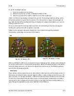
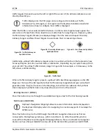
Runway edge lines
Runway centerline
Runway numbers
Runway thresholds / displaced thresholds
Aiming point markings: two white strips drawn 1000’ after the threshold on runways
4000’ and longer
Runway width threshold markings: drawn immediately after the runway threshold,
these groups of parallel lines visually indicate the width of the runway in the following
manner according to runway width:
o
0’-59’ wide: no lines
o
60’-74’ wide: 4 lines
o
75’-99’ wide: 6 lines
o
100’-149’ wide: 8 lines
o
150’-199’: 10 lines
o
200’+: 12 lines
Obstacles on Synthetic Vision
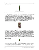
Obstacles are only depicted when the Navigation Mapping Software is licensed or in its 30 flight
hour free introductory trial mode. See the SV-MAP-270 Navigation Mapping Software section
for more information about map licensing and obtaining obstacle data.
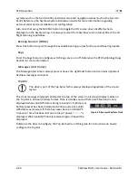
Obstacles are only shown on Synthetic Vision if their highest point is within 1000 feet below
your aircraft’s GPS altitude. If the highest point of an obstacle is within 100 feet below your
current GPS altitude to anywhere above you, it will be red. If the highest point of the obstacle is
between 100 and 1000 feet below your current GPS altitude, the obstacle will be yellow. This is
the same color scheme used on the Map Page as described in the Topography with Terrain
Proximity Alerts Section.
Obstacles are shown at their actual height above the ground. In other words, if the flight path
marker is above the top of an obstacle in the Synthetic Vision version, your aircraft should clear
it in real life as well.
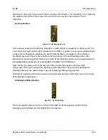
The tower symbology used to denote different types of obstacles is the same as used in the
Moving Map depiction. See the Moving Map Symbology section of this guide for more
information.
Traffic on Synthetic Vision
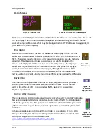
When a device that can receive traffic information is installed and configured, traffic can be
displayed within the Synthetic Vision display to improve situational awareness.

