
PFD Operation
4-10
SkyView Pilot’s User Guide - Revision M
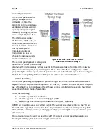
The vertical speed bug is used by the autopilot as a target vertical speed when it is climbing or
descending. Reference the Autopilot Operation Chapter for more information regarding
autopilot functionality, symbology, and operation information.
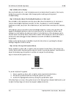
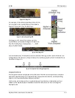
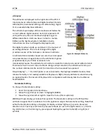
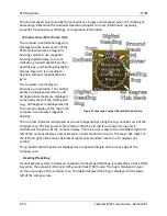
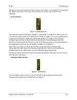
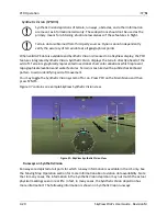
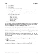
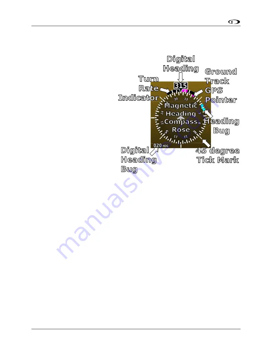
Compass Rose/Directional Gyro
The compass rose/directional gyro is
displayed on the lower center of the
PFD and incorporates a magnetic
heading compass rose, magnetic
heading digital display, turn rate
indicator, ground track GPS pointer,
heading bug, and heading bug digital
display. Figure 17 is an example
SkyView compass rose/directional
gyro.
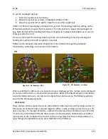
The compass rose displays in
heading-up orientation. The cardinal
points are displayed as letters, and
30 degree increments are displayed
numerically without the trailing zero
(e.g., 330 degrees is displayed as 33).
The numeric display at the top of the
compass rose indicates magnetic
heading.
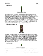
The turn rate indicator is displayed as a curved magenta bar along the top, outside curve of the
compass rose. The bar grows in the direction that the aircraft is currently turning and is
anchored at the arrow of the numeric display. The minor tick marks to the immediate right and
left of the numeric display arrow represents a half-standard-rate-turn. The major tick marks to
the left and right of the minor tick marks represent a standard rate turn of 3 degrees per
second.
The ground track GPS pointer is displayed as a magenta triangle on the inner edge of the
compass rose.
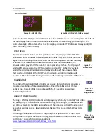
Heading/Track Bug
If your SkyView system includes an autopilot, the heading (HDG) bug is replaced by a track (TRK)
bug when the autopilot is flying in GPS ground track (TRK) mode. The bug is displayed in cyan
on the inner edge of the compass rose. The digital display of the bug is displayed to the lower
left of the compass rose.
Figure 17–Example Compass Rose/Directional Gyro


