PFD Operation
SkyView Pilot’s User Guide - Revision M
4-13
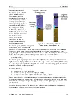
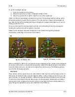
direction as the arrow at the end of the course line, then that is a "to" indication. If it is pointing
the opposite direction of the arrow at the end of the course line, then that is a "from"
indication.
Bearing Pointers
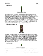
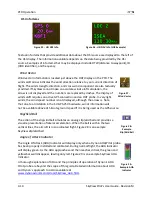
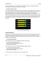
Figure 23 - HSI Bearing Pointer
These arrows show you the bearing directly to a radio station or waypoint–in other words, the
track that you would need to fly to go directly to it. BRG 1 is yellow in color and is depicted with
a single arrow head when displayed on the HSI display. BRG 2 is orange in color and has a
double arrow head. There is also a textual information item for each bearing pointer that
describes its source (eg. GPS0, NAV1, etc.). Each of the bearing pointers can be cycled between
all available bearing sources by pressing BRG 1 or BRG2 in the PFD Menu.
Note that some radios, such as the Garmin SL30, provide information about standby
frequencies that can be loaded into bearing pointer locations. These are only available for
standby VORs that are within range. They are labeled as SBY bearing pointers.
NAV radios tuned to a LOC/ILS frequency do not provide bearing information due to the nature
of the localizer radio signal.
Glideslope/VNAV Indicator
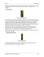
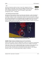
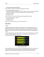
Figure 24 - HSI Glide Slope
This only appears when tuned to an ILS or a GPS with vertical navigation output. When
displaying an ILS glideslope, full deflection is 0.5 degrees.

