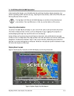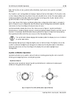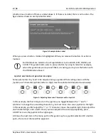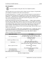
PFD Operation
4-4
SkyView Pilot’s User Guide - Revision M
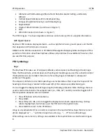
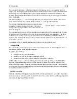
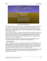
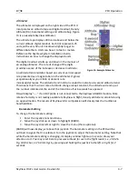
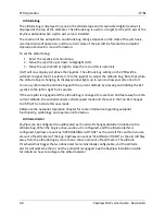
The airspeed tape displays indicated airspeed including gray, white, green, yellow, and red
ranges to provide a graphical representation of aircraft speed in relation to the aircraft's limits.
These ranges are controlled by setting the airspeed limitations for the aircraft. Refer to the
SkyView System Installation Guide for instructions on how to configure the airspeed limitation
color thresholds.
Airspeed will display “---“ at zero through 20 knots, at which point it will become alive. Once
alive, it will read down to 15 knots. Below 15 knots, “---“ will again be displayed.
The indicated airspeed (IAS) digits scroll up and down,
simulating an analog Airspeed Indicator. The rate of
change of the digits provides a sense of the increase or
decrease in speed.
The airspeed trend indicator (ATI) is displayed as a magenta bar on the airspeed tape. It grows
proportionally in the direction of the rate of change (acceleration or deceleration). The ATI is
scaled to indicate a 6-second airspeed trend which means that if the acceleration is kept
constant, the airspeed will end up at the number indicated at the end of the trend line after 6
seconds have passed.
True airspeed (TAS) is digitally displayed at the bottom of the airspeed tape.
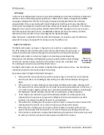
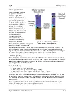
Airspeed Bug
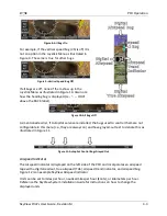
The airspeed bug is displayed in cyan on the airspeed tape and its associated digital readout is
displayed at the top of the Airspeed Indicator.
To set the airspeed bug:
1.
Enter the Joystick Function Menu.
2.
Move the joystick up or down to highlight (ASPD).
3.
Move the joystick left or right to close the menu (this is optional).
(ASPD) will now display just above that joystick. The airspeed bug setting on the PFD will be
outlined to signal that it is selected. Turn the joystick to adjust the airspeed bug. Note that
while the airspeed bug is changing, its display window lights up in cyan to draw your attention
to it.
You may also synchronize the bug to current airspeed by pressing and holding the joystick
to the left or right for 2 seconds.
Attitude Indicator
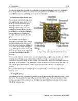
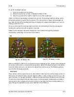
Attitude indicator symbology is displayed on PFD and incorporates a roll scale with roll pointers
and a zero pointer reference, pitch scale with horizon lines, and water line symbology. Figure 13
is an example SkyView attitude indicator.
Figure 12–Example Airspeed Indicator


