DRV-28 inverter
s Function parameter list
-145-
Function
code
Name
Detailed parameter description
Default
value
Modi
fy
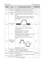
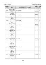
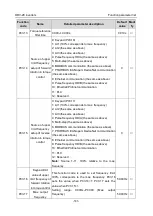
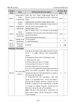
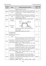
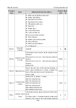
P03.41
Upper limit of
inertia
compensation
torque
Limit the max. inertia compensation torque to
prevent inertia compensation torque from being too
large.
Setting range: 0.0–150.0% (rated motor torque)
10.0%
○
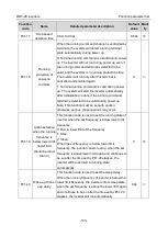
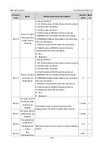
P03.42
Inertia
compensation
filter times
Filter times of inertia compensation torque, used to
smooth inertia compensation torque.
Setting range: 0–10
7
○
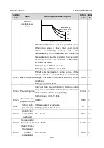
P03.43
Inertia
identification
torque value
Due to friction force, it is required to set certain
identification torque for the inertia identification to be
performed properly.
0.0–100.0% (rated motor torque)
10.0%
○
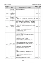
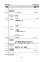
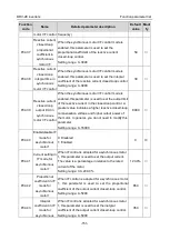
P03.44
Enable inertia
identification
0: No operation
1: Start identification
0
◎
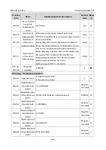
P03.45–
P03.46
Reserved
variables
0–65535
0
●
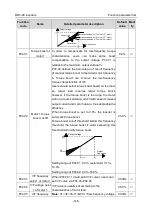
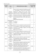
P04 group V/F control
P04.00
V/F curve setup
of motor 1
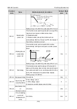
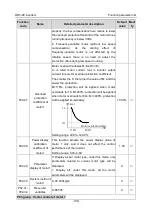
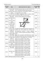
This group of function code defines the V/F curve of
motor 1 to satisfy different load characteristics
needs.
0: Straight V/F curve; fit for constant-torque load
1: Multi-point V/F curve
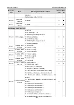
2: Torque down V/F curve (1.3
th
order)
3: Torque down V/F curve (1.7
th
order)
4: Torque down V/F curve (2.0
nd
order)
Curve 2–4 are suitable for torque-variable load of fan
pump and similar equipment. Users can make
adjustment based on load characteristics to achieve
optimal energy-saving effect.
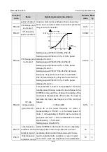
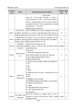
5: Customized V/F (V/F separation); under this
mode, V is separated from f. Users can adjust f
through the frequency reference channel set by
P00.06 to change the curve characteristic, or adjust
V through the voltage reference channel set by
P04.27 to change the curve characteristics.
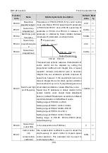
Note: The V
b
in the figure below corresponds to
rated motor voltage, and
f
b
corresponds to rated
motor frequency.
0
◎


