DRV-28 inverter
s Basic operartion instructions
-82-
Function
code
Name
Detailed parameter description
Default
value
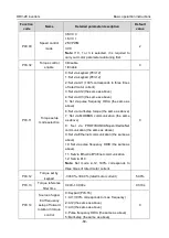
P08.01
Declaration time 2
0.0–3600.0s
Depend
on model
P08.02
Acceleration time 3
0.0–3600.0s
Depend
on model
P08.03
Declaration time 3
0.0–3600.0s
Depend
on model
P08.04
Acceleration time 4
0.0–3600.0s
Depend
on model
P08.05
Declaration time 4
0.0–3600.0s
Depend
on model
P08.19
Switching frequency of
acceleration/deceleration
time
0.00–P00.03 (Max. output frequency)
0.00Hz: No switch over
If the running frequency is larger than
P08.19, switch to acceleration
/deceleration time 2
0
P08.21
Reference frequency of
acceleration/deceleration
time
0: Max. output frequency
1: Set frequency
2: 100Hz
Note: Valid for straight-line
acceleration/deceleration only
0
P08.28
Automatic fault reset times 0–10
0
P08.29
Automatic fault reset time
interval
0.1–3600.0s
1.0s
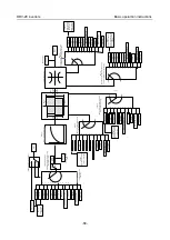
5.5.8 Frequency setup
DRV-28 series inverter supports multiple kinds of frequency reference modes, which can be
categorized into two types: main reference channel and auxiliary reference channel.
There are two main reference channels, namely frequency reference channel A and frequency
reference channel B. These two channels support simple arithmetical operation between each other,
and they can be switched dynamically by setting multi-function terminals.
There is one input mode for auxiliary reference channel, namely terminal UP/DOWN switch input. By
setting function codes, users can enable the corresponding reference mode and the impact made on
the inverter frequency reference by this reference mode.
The actual reference of inverter is comprised of the main reference channel and auxiliary reference
channel.


