DRV-28 inverter
s Function parameter list
-176-
Function
code
Name
Detailed parameter description
Default
value
Modi
fy
coefficient on
input side
0.00–1.00
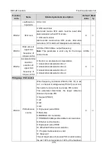
P08.52
STO lock
0: STO alarm lock
Alarm-lock means STO alarm must be reset after
state restoration when STO occurs.
1: STO alarm unlock
Alarm-unlock means when STO occurs, after state
restoration, STO alarm will disappear automatically.
0
○
P08.53
Bias value of
upper limit
frequency of
torque control
0.00 Hz–P00.03 (Max. output frequency)
Note:
This parameter is valid only for the torque
control mode.
0.00Hz
○
P08.54
Acceleration/dec
eleration
selection of
upper limit
frequency of
torque control
0: No limit on acceleration or deceleration
1: Acceleration/deceleration time 1
2: Acceleration/deceleration time 2
3: Acceleration/deceleration time 3
4: Acceleration/deceleration time 4
0
○
P09 group PID control
P09.00
PID reference
source
When frequency command (P00.06, P00. 07) is set
to 7, or channel of voltage setup (P04.27) is set to 6,
the inverter running mode is process PID control.
This parameter determines the target reference
channel of process PID.
0: Keypad (P09.01)
1: AI1
2: AI2
3: AI3
4: High-speed pulse HDIA
5: Multi-step
6: MODBUS communication
7: PROFIBUS/CANopen/DeviceNet communication
8: Ethernet communication
9: High-speed pulse HDIB
10: EtherCat/Profinet communication
11: Programmable extension card
12: Reserved
The set target value of process PID is relative value,
the set 100% corresponds to 100% of the feedback
0
○

