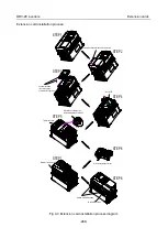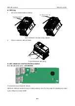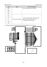
DRV-28 inverter
s Extension cards
-296-
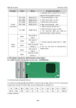
A.5.3 Resolver PG card
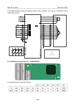
–– AS28ENC0002
PE
AO+
BO+
ZO+
EX+
SI+
CO+
A2+
B2+
Z2+
PWR
GND
AO-
BO-
ZO-
EX-
SI-
CO-
A2-
B2-
Z2-
PGND
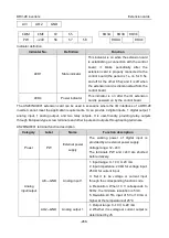
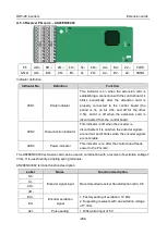
Indicator definition
Indicator No.
Definition
Function
LED1
State indicator
This indicator is on when the extension card is
establishing a connection with the control board; it
blinks periodically after the extension card is
properly connected to the control board (the
period is 1s, on for 0.5s, and off for the other
0.5s); and it is off when the extension card is
disconnected from the control board.
LED2
Disconnection indicator
This indicator is off when the encoder is
disconnected; it is on when the encoder signals
are normal; and it blinks when the encoder signals
are not stable.
LED3
Power indicator
This indicator is on after the control board feeds
power to the PG card.
The AS28ENC0002 extension card can be used in combination with a resolver of excitation voltage 7
Vrms. It is user-friendly, adopting spring terminals.
AS28ENC0002 terminal function description
Label
Name
Function description
SI+
Encoder signal input
Recommended resolver transformation ratio: 0.5
SI-
CO+
CO-
EX+
Encoder excitation
signal
1. Factory setting of excitation: 10 kHz
2. Supporting resolvers with an excitation voltage
of 7 Vrms
EX-
A2+
Pulse setting
1. Differential input of 5 V

