DRV-28 inverter
s Function parameter list
-172-
Function
code
Name
Detailed parameter description
Default
value
Modi
fy
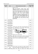
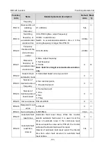
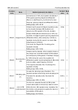
After inverter starts, if no fault occurred during 60s,
the fault reset times will be zeroed out.
Setting range of P08.28: 0
–10
Setting range of P08.29: 0.1–3600.0s
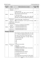
P08.30
Reduction ratio of
droop control
This function code sets the variation rate of the
inverter output frequency based on the load; it is
mainly used in balancing the power when multiple
motors drive the same load.
Setting range: 0.00–50.00Hz
0.00Hz
○
P08.31
Switch-over
between motor 1
and motor 2
0x00–0x14
Ones: Switch-over channel
0: Switch over by terminal
1: Switch over by MODBUS communication
2: Switch over by PROFIBUS/CANopen/DeviceNet
3: Switch over by Ethernet communication
4: Switch over by EtherCat/Profinet communication
Tens: Motor switch over during running
0: Disable switch over during running
1: Enable switch over during running
0x00
◎
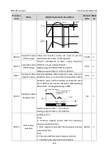
P08.32
FDT1 level
detection value
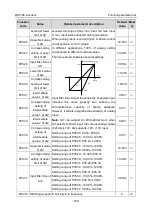
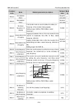
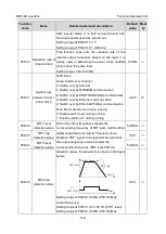
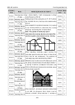
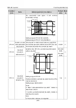
When the output frequency exceeds the
corresponding frequency of FDT level, multi-function
digital output terminal outputs "frequency level
detection FDT" signal, this signal will be valid until
the output frequency lowers to below the
corresponding frequency (FDT level-FDT lag
detection value), the waveform is shown in the figure
below.
Time t
Output frequency f
FDT level
FDT lag
Y1,
RO1, RO2
Time t
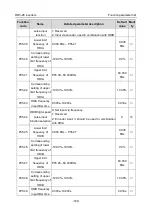
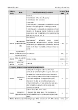
Setting range of P08.32: 0.00Hz–P00.03 (Max.
output frequency)
Setting range of P08.33: 0.0–100.0% (FDT1 level)
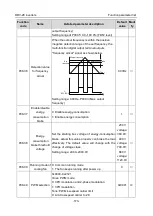
Setting range of P08.34: 0.00Hz–P00.03 (Max.
50.00Hz
○
P08.33
FDT1 lag
detection value
5.0%
○
P08.34
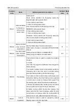
FDT2 level
detection value
50.00Hz
○
P08.35
FDT2 lag
detection value
5.0%
○

