DRV-28 inverter
s Function parameter list
-182-
Function
code
Name
Detailed parameter description
Default
value
Modi
fy
11
th
step
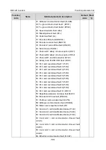
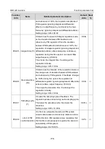
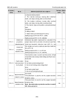
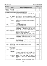
terminal 3 and terminal 4 are not all OFF, the
frequency set by multi-step speed will prevail, and
the priority of multi-step setting is higher than that of
the keypad, analog, high-speed pulse, PID, and
communication settings.
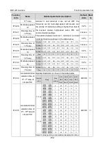
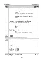
The relation between terminal 1, terminal 2, terminal
3 and terminal 4 are shown in the table below.
Terminal 1 OFF ON
OFF
ON
OFF
ON
OFF
ON
Terminal 2 OFF OFF
ON
ON
OFF OFF
ON
ON
Terminal 3 OFF OFF OFF OFF
ON
ON
ON
ON
Terminal 4 OFF OFF OFF OFF OFF OFF OFF OFF
Step
0
1
2
3
4
5
6
7
Terminal 1 OFF ON
OFF
ON
OFF
ON
OFF
ON
Terminal 2 OFF OFF
ON
ON
OFF OFF
ON
ON
Terminal 3 OFF OFF OFF OFF
ON
ON
ON
ON
Terminal 4 ON
ON
ON
ON
ON
ON
ON
ON
Step
8
9
10
11
12
13
14
15
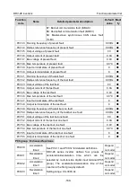
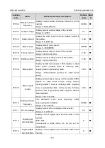
P10.26
Multi-step speed
12
0.0%
○
P10.27
Running time of
12
th
step
0.0s(min)
○
P10.28
Multi-step speed
13
0.0%
○
P10.29
Running time of
13
th
step
0.0s(min)
○
P10.30
Multi-step speed
14
0.0%
○
P10.31
Running time of
14
th
step
0.0s(min)
○
P10.32
Multi-step speed
15
0.0%
○
P10.33
Running time of
15
th
step
0.0s(min)
○
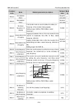
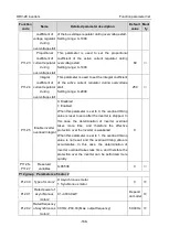
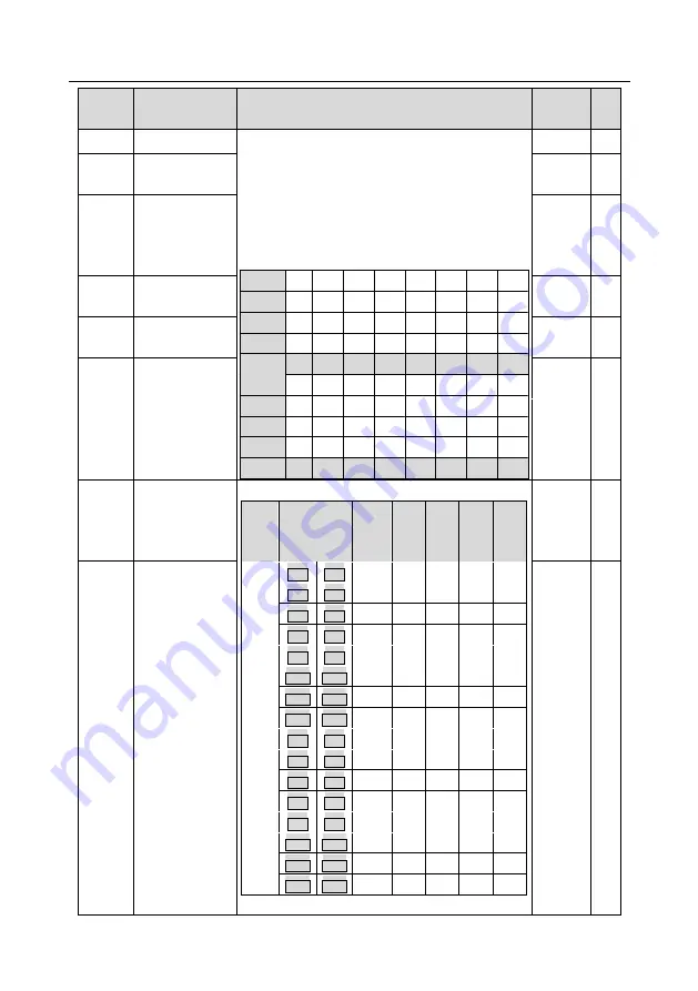
P10.34
Acceleration/dec
eleration time of
0
th
–7
th
step of
simple PLC
Detailed illustration is shown in the table below.
Function
code
Binary
Step
number
ACC/
DEC
time 1
ACC/
DEC
time 2
ACC/
DEC
time 3
ACC/
DEC
time 4
P10.34
BIT1
BIT0
0
00
01
10
11
BIT3
BIT2
1
00
01
10
11
BIT5
BIT4
2
00
01
10
11
BIT7
BIT6
3
00
01
10
11
BIT9
BIT8
4
00
01
10
11
BIT11 BIT10
5
00
01
10
11
BIT13 BIT12
6
00
01
10
11
BIT15 BIT14
7
00
01
10
11
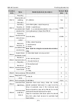
P10.35
BIT1
BIT0
8
00
01
10
11
BIT3
BIT2
9
00
01
10
11
BIT5
BIT4
10
00
01
10
11
BIT7
BIT6
11
00
01
10
11
BIT9
BIT8
12
00
01
10
11
BIT11 BIT10
13
00
01
10
11
BIT13 BIT12
14
00
01
10
11
BIT15 BIT14
15
00
01
10
11
Select corresponding acceleration/deceleration time,
0x0000
○
P10.35
Acceleration/dec
eleration time of
8
th
– 15
th
step of
simple PLC
0x0000
○

