DRV-28 inverter
s Function parameter list
-197-
Function
code
Name
Detailed parameter description
Default
value
Modi
fy
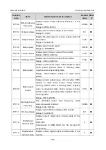
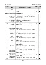
P17.02
Ramps reference
frequency
Display current ramps reference frequency of the
inverter.
Range: 0.00Hz–P00.03
0.00Hz
●
P17.03
Output voltage
Display current output voltage of the inverter.
Range: 0–1200V
0V
●
P17.04
Output current
Display the valid value of current output current of
the inverter.
Range: 0.0–5000.0A
0.0A
●
P17.05
Motor speed
Display current motor speed.
Range: 0–65535RPM
0 RPM
●
P17.06
Torque current
Display current torque current of the inverter.
Range: -3000.0–3000.0A
0.0A
●
P17.07 Exciting current
Display current exciting current of the inverter.
Range: -3000.0–3000.0A
0.0A
●
P17.08
Motor power
Display current motor power; 100% relative to rated
motor power, positive value is motoring state,
negative value is generating state.
Range: -300.0–300.0% (relative to rated motor
power)
0.0%
●
P17.09
Motor output
torque
Display current output torque of the inverter; 100%
relative to rated motor torque, during forward
running, positive value is motoring state, negative
value is generating state, during reverse running,
positive value is generating state, negative value is
motoring state.
Range: -250.0–250.0%
0.0%
●
P17.10
Estimated motor
frequency
The estimated motor rotor frequency under
open-loop vector condition.
Range: 0.00– P00.03
0.00Hz
●
P17.11 DC bus voltage
Display current DC bus voltage of the inverter.
Range: 0.0–2000.0V
0V
●
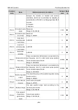
P17.12
Digital input
terminal state
Display current digital input terminal state of the
inverter.
0000–03F
Corresponds to HDIB, HDIA, S4, S3, S2 and S1
respectively
0
●
P17.13
Digital output
terminal state
Display current digital output terminal state of the
inverter.
0
●

